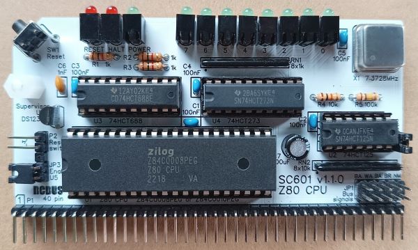
SC601 is a Z80 Central Processor Unit (CPU) module with clock oscillator, status LEDs, and a voltage supervisor and reset device, designed for the 40-pin RCBus.
- SC601 – Assembly guide
- SC601 – Compatibility
- SC601 – Parts list
- SC601 – Printed circuit board
- SC601 – User guide
- SC600 series information
- SC600 series support
Downloads
- SC601, v1.1.x, Kit contents sheet (PDF)
- SC601, v1.1.0, Schematic (PDF)
- SC601, v1.1.1, Schematic (PDF)
- SC601, v1.1.0, PCB design files (OSHWLab)
- SC601, v1.1.1, PCB design files (OSHWLab)
- SC601, v1.1.0, Gerber files (ZIP)
- SC601, v1.1.1, Gerber files (ZIP)
Errata
PCB v1.1.0: RN2 changed from 10k to 4k7 to improve the rise time of the /WRLED signal.
Suppliers
| Kits | Website | From | Currency |
| Small Computers Direct | SCDirect | UK | GBP |
| Stephen C Cousins | Tindie | UK | USD |
| Small Computer Central | Lectronz | UK | Euro/USD |
| PCBs | Website | From | Currency |
| Small Computers Direct | SCDirect | UK | GBP |
| Stephen C Cousins | Tindie | UK | USD |
| Small Computer Central | Lectronz | UK | Euro/USD |
| Assembled and Tested | Website | From | Currency |
| Not available | |||
| Components | |||
| See parts list |
Tindie does not collect VAT for EU countries
Lectronz does collect EU VAT for orders up to 150 EUR
Parts List
| Reference | Qty | Component |
| PCB | 1 | SC601, v1.1, PCB |
| C1 to C5 | 5 | Capacitor, ceramic, 100 nF |
| C6 | 1 | Capacitor, ceramic, 1 nF |
| C7 | 1 | Capacitor, electrolytic, 100 µF |
| JP1 | 1 | Header, male, 2 row x 5 pin, straight |
| JP2 | 1 | Header, male, 1 row x 2 pin, straight |
| JP3 | 1 | Header, male, 1 row x 2 pin, angled or 5 pin (JP3 + P2) |
| Jumper | 5 | Jumper shunt |
| LED0 to LED8 | 9 | LED, green, 3mm, angled |
| LED9 and LED10 | 2 | LED, red, 3mm, angled |
| P1 | 1 | Header, male, 1 row x 40 pin, angled |
| P2 | 1 | Header, male, 1 row x 2 pin, angled or 5 pin (JP3 + P2) |
| R1 to R3 | 3 | Resistor, 1k, 0.25W |
| R4 | 1 | Resistor, 10k, 0.25W |
| R5 | 1 | Resistor, 100k, 0.25W |
| RN1 | 1 | Resistor network, 8x1k, SIL, 9-pin |
| RN2 | 1 | Resistor network, 8x4k7, SIL, 9-pin formerly: Resistor network, 8x10k, SIL, 9-pin |
| SW1 | 1 | Switch, tactile button, angled |
| Screw (for spacer) | 1 | Machine screw, 6mm, M3 |
| Spacer | 1 | Spacer, 10mm, M3, nylon |
| U1 | 1 | Z80 CPU, Z84C0008PEG, or Z80 CPU, Z84C0010PEG |
| U2 | 1 | 74HCT125 |
| U3 | 1 | 74HCT688 |
| U4 | 1 | 74HCT273 |
| U5 | 1 | DS1233-5+ supervisor |
| X1 | 1 | Oscillator, 7.3728MHz |
| IC socket 40-pin U1 | 1 | Socket, DIP, 40 pin |
| IC socket 14-pin U2 | 1 | Socket, DIP, 14-pin |
| IC socket 20-pin U3 and U4 | 2 | Socket, DIP, 20-pin |
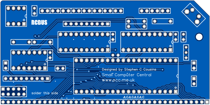
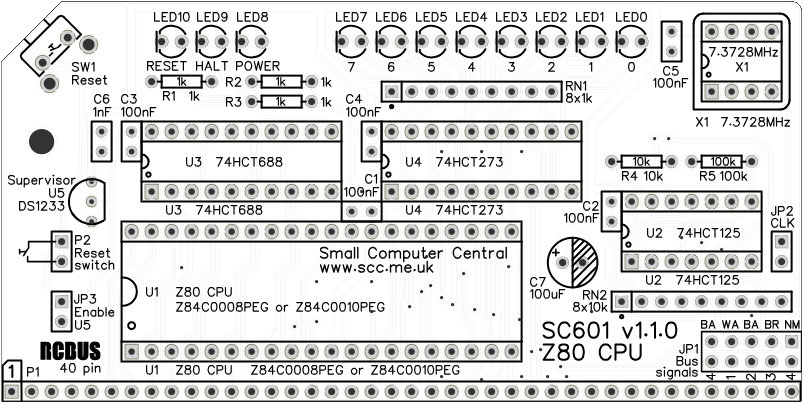
Printed Circuit Board
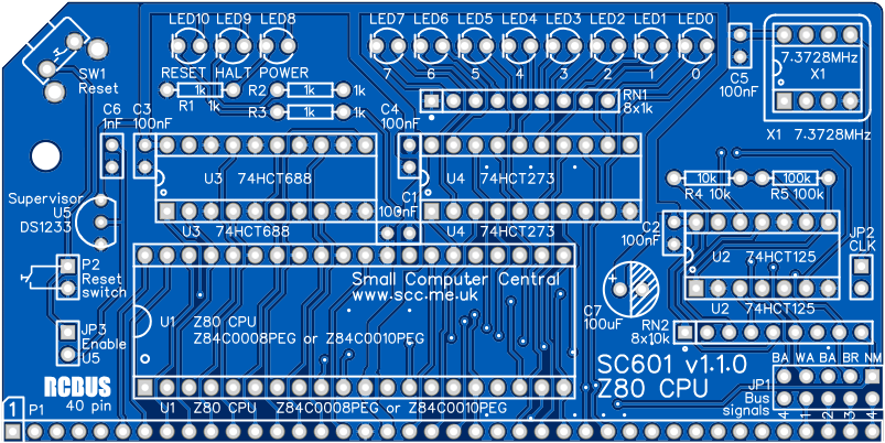
PCB dimensions: 4.0″ x 2.0″ (101.6mm x 50.8mm)
User Guide
SC601 is a Z80 Central Processor Unit (CPU) module with clock oscillator, status LEDs, and a voltage supervisor and reset device, designed for the RCBus 40-pin.
The voltage supervisor and reset device (U5) provides a reliable power up reset. It works by holding the CPU in reset until the supply voltage reaches approximately 4.75 volts. If the system does not seem to be working, always check the supply voltage is above 4.75 volts on the PCB and that the RESET signal is a logic high voltage, typically above 4 volts. The supervisor should hold the reset low of about 0.3 seconds after the system is turned on and after the reset button is released.
The system should only include one enabled voltage supervisor, so a jumper option has been provided to connect or isolate this device. Normally, it should be connected, but if you have a supervisor on another module you may need to isolate this one.
Status LEDs
| LED | Address | Function |
| 0 | Port 0 bit 0 | Programmable |
| 1 | Port 0 bit 1 | Programmable |
| 2 | Port 0 bit 2 | Programmable |
| 3 | Port 0 bit 3 | Programmable |
| 4 | Port 0 bit 4 | Programmable |
| 5 | Port 0 bit 5 | Programmable |
| 6 | Port 0 bit 6 | Programmable |
| 7 | Port 0 bit 7 | Programmable |
| 8 | n/a | Power on indicator |
| 9 | n/a | CPU HALT signal |
| 10 | n/a | CPU RESET signal |
The module incudes 11 LEDs. Three of the LEDs show power, halt and reset, while the other 8 are programmable. The programmable LEDs can be controlled by writing to port 0. They are used in various ways by different firmware and software. Uses include: self-test, progress during start up, disk activity and general outputs. Self-test can be particularly helpful if the system is not running correctly. For example, SCM will use these even if the system has no working RAM and no working serial port.
Input/output port functions
| I/O Address | Read | Write |
| 0x00 | n/a | Status LEDs |
Jumper options
| Jumper | Function | Label |
| JP 1 | User pin bus signals JP1.1 connects USER4 to /NMI JP1.2 connects USER3 to /BUSRQ JP1.3 connects USER2 to /BUSAK JP1.4 connects USER1 to /WAIT JP1.5 connects USER4 to /BUSAK | 4 – NM 3 – BR 2 – BA 1 – WA 4 – BA |
| JP 2 | Enable the clock oscillator | CLK |
| JP 3 | Enable the voltage supervisor and reset device (U5, DS1233) | Enable U5 |
Fit jumper shunts to JP1 only if you specifically require one or more of the listed signals connected to the USER pin(s) on the bus.
Fit jumper shunt to JP2 to connect the on board clock oscillator to the CPU and the bus. Do not fit the shunt if your system is using a different clock source, such as one generated from a dedicated clock module.
Fit a jumper shunt to JP3 if the voltage supervisor is to be used. This jumper connects the voltage supervisor to the RESET signal. The system should only contain one enabled supervisor, thus the jumper has been provided to isolate or connect this device.
Assembly Guide
Below is the suggested order of assembly. A general guide to assembling circuit boards can be found here.
- Resistors R1, R2, R3, R4 and R5
These can be fitted either way around - Decoupling capacitors C1, C2, C3, C4 and C5 (100 nF)
These can be fitted either way around - Ceramic capacitor C6 (1 nF)
These can be fitted either way around - Header pins JP3 and P2 (1 row x 5 pin, angled)
This can be a single strip of 5 pins with the middle pin removed - Bus header P1 (1 row x 40 pin, angled)
Make sure the pins are parallel to the PCB so that the board is vertical when it is fitted into a backplane socket - Sockets for U1, U2, U3 and U4
Fit such that the notch in the socket matches the curve in the outline on the PCB silkscreen - Resistor networks RN1 and RN2
These must be fitted the correct way around whereby the dot on the component matches the dot on the PCB silkscreen - Capacitor C7 (100 uF)
This must be fitted the correct way around, as described here - Header pins JP1 and JP2
- Light emitting diodes LED0 to LED8 (green) and LED9 and LED10 (red)
The angled LEDs in the kit only fit one way around, but standard LEDs need to have the short lead in the hole marked with a flat line - Switch SW1
- Voltage supervisor U5
Carefully bend the legs to match the hole spacing on the PCB and ensure the orientation matches the markings on the PCB. Do NOT strain the legs by pressing Q1 hard against the PCB. - Fit oscillator X1
Ensure the orientation matches the silkscreen - Fit a jumper shunt to JP2 and another to JP3
- Insert the integrated circuits into their sockets
Make sure the notch in the component is at the end indicated by the notch in the socket and the curve on the PCB silkscreen - Fit the nylon spacer in the mounting hole
Fit jumper shunts in the positions shown below. All other jumpers are optional and should only be fitted if the feature is required.

Compatibility
This module conforms to the RCBus specification v1.0 for RCBus-2014 (40-pin bus) and RCBus-Z80 (40-pin bus).
The RCBus specification includes RCBus-2014 (both RC2014 standard 40-pin bus and RC2014 enhanced 60-pin bus) and also the full 80-pin RCBus. The 80-pin RCBus provides support for advanced Z80 features, such as the interrupt daisy-chain, as well as support for other processor families.
The table below indicates electrical compatibility with each backplane type (40, 60 and 80 pin)

| Backplane | ? | Compatibility notes |
| RCBus 80-pin |  | Fully supported |
| RCBus 60-pin (RC2014 enhanced) | | Fully supported |
| RCBus 40-pin (RC2014 standard) | | Fully supported |
Notes
- This product is designed for hobby use and is not suitable for industrial, commercial, or safety-critical applications.
- The product contains small parts and is not suitable for young children.
- RC2014 is a trademark of RFC2795 Ltd.
