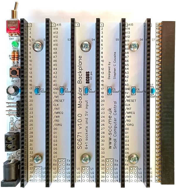
SC671 is a 40-pin RCBus modular backplane with 6 vertical bus sockets, 1 horizontal bus socket, and a 5-volt power input.
- SC671 – Assembly guide
- SC671 – Compatibility
- SC671 – Interrupt daisy chain
- SC671 – Parts list
- SC671 – Printed circuit board
- SC671 – User guide
- SC600 series information
- SC600 series support
Downloads
- SC671, v1.0, Kit contents sheet (PDF)
- SC671, v1.0, Schematic (PDF)
- SC671, v1.0, PCB design files (OSHWLab)
- SC671, v1.0, Gerber files (ZIP)
Warnings
Assembly: Ensure the bus sockets are pressed firmly against the PCB along their entire length
Errata
Nothing known
Suppliers
| Kits | Website | From | Currency |
| Small Computers Direct | SCDirect | UK | GBP |
| Stephen C Cousins | Tindie | UK | USD |
| Small Computer Central | Lectronz | UK | Euro/USD |
| PCBs | Website | From | Currency |
| Small Computers Direct | SCDirect | UK | GBP |
| Stephen C Cousins | Tindie | UK | USD |
| Small Computer Central | Lectronz | UK | Euro/USD |
| Assembled and Tested | Website | From | Currency |
| Not available | |||
| Components | |||
| See parts list |
Tindie does not collect VAT for EU countries
Lectronz does collect EU VAT for orders up to 150 EUR
User Guide
The backplane can supply power to the whole RCBus system by connecting a regulated 5 volt supply to either J1 or J2. J1 is a 2.1mm barrel socket, centre positive, while J2 is a pair of screw terminals.
The regulated 5 volt supply must provide a voltage between 4.75 and 5.25 volts, and must be able to maintain that voltage at the maximum current drawn by the RCBus system, typically 500 mA, but possibly higher.
Power is connected to the modules when the ON/OFF switch, SW1, is in the ON position. The LED lights
Header pins P1 allow an external reset switch to be connected to the backpane.
Optional voltage supervisor: The voltage supervisor and reset device (Q1) provides a reliable power up reset. It works by holding the CPU in reset until the supply voltage reaches approximately 4.75 volts. If the system does not seem to be working, always check the supply voltage is above 4.75 volts on the PCB and that the RESET signal is a logic high voltage, typically above 4 volts. The supervisor should hold the reset low of about 0.5 seconds after the system is turned on and after the reset button is released.
The system should only include one enabled voltage supervisor, so the backplane includes header pins, JP1, to enable the supervisor to be connected (jumper shunt fitted) or disabled (jumper shunt not fitted). Normally, it should be connected, but if you have a supervisor on another module you may need to isolate this one.
Note: The kit does not include the voltage supervisor as it is assumed this function is provided by the CPU module.
Input/output port functions
| I/O Address | Read | Write |
| none | n/a | n/a |
Jumper options
| Jumper | Function |
| JP1 | Connect voltage supervisor, Q1, to the reset signal |
| JP 2, 4, 6 | JPx.1 Connect U1 signal between bus sockets JPx.2 Connect U2 signal between bus sockets JPx.3 Connect U3 signal between bus sockets JPx.4 Connect U4 signal between bus sockets Thin tracks on the under side of the PCB link these jumper positions, thus signals U1, U2, U3 and U4 are connected to each backplane socket |
| JP 3, 5 | JPx.1 Connect TX signal between bus sockets JPx.2 Connect RX signal between bus sockets JPx.3 Connect U1 signal between bus sockets JPx.4 Connect U2 signal between bus sockets JPx.5 Connect U3 signal between bus sockets JPx.6 Connect U4 signal between bus sockets Thin tracks on the under side of the PCB link these jumper positions, thus signals TX, RX, U1, U2, U3 and U4 are connected to each backplane socket |
JP2 to JP10 allow some signals to be isolated between bus sockets. This can be helpful if there are several modules that use these signals for different functions.
Thin tracks on the under side of the PCB link these jumper positions, thus signals TX (pin 35), RX (pin 36), U1 (pin 37), U2 (pin 38), U3 (pin 39) and U4 (pin 40) are connected to each backplane socket. To isolate any of these signals it is necessary to cut the associated thin track. Most users will not need to do this. It is only more complex set ups that need any of these signals isolated.
Bus signals U1 to U4 have no specified function on the original RC2014 bus and were known as SPARE or USER signals.
Assembly Guide
Below is the suggested order of assembly. A general guide to assembling circuit boards can be found here.
- Resistors R1 and R2
These can be fitted either way around - Bus socket S7
Ensure the bus socket is pressed firmly against the PCB along their entire length - Decoupling capacitors C1 to C7
These can be fitted either way around - Capacitor C9 (not included in the kit)
This can be fitted either way around - Header pins JP1 plus P1
- Switch SW2
- Switch SW1
- Capacitor C8
This must be fitted the correct way around, as described here - LED1
This must be fitted the correct way around, as described here - Bus sockets S1 to S6
Ensure the bus sockets are pressed firmly against the PCB along their entire length - Screw terminal J2
Ensure the screw terminals face the edge of the PCB - Barrel socket J1
- Voltage supervisor Q1 (not included in the kit)
Carefully bend the legs to match the hole spacing on the PCB and ensure the orientation matches the markings on the PCB. Do NOT strain the legs by pressing Q1 hard against the PCB.
Parts List
C9 and Q1 are not included in the kit as it is assumed the voltage supervisor is included on the CPU module.
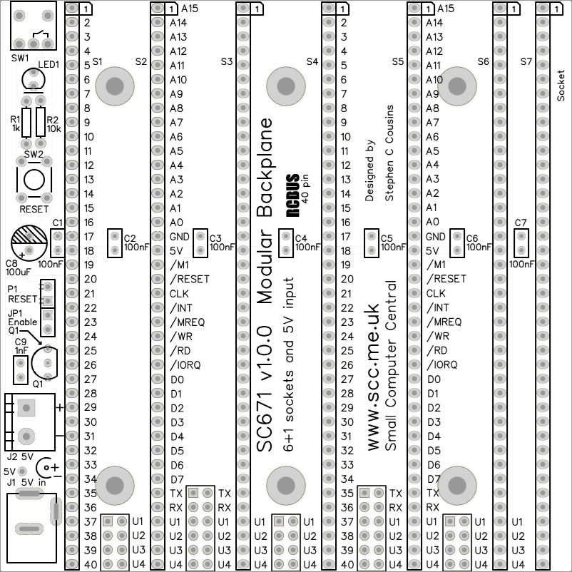
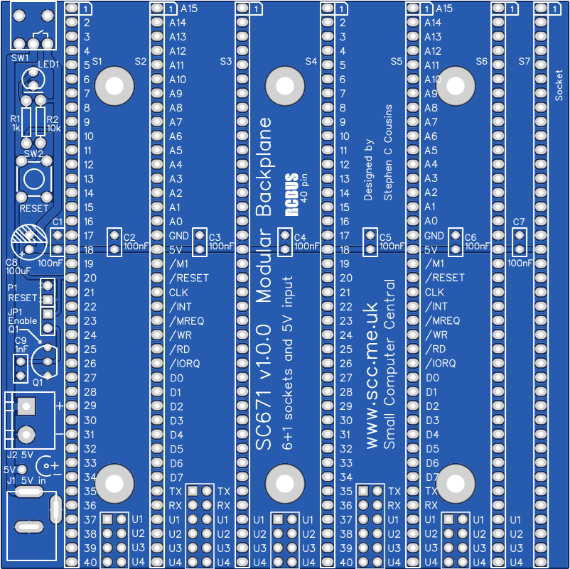
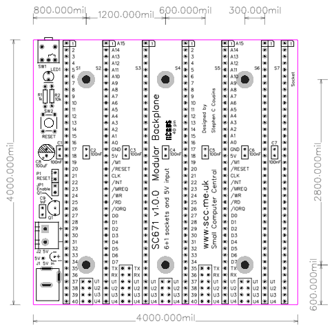
Printed Circuit Board

Compatibility
This backplane conforms to the RCBus specification v1.0 for 40-pin systems. Namely, RCBus-2014 standard bus.
The RCBus specification includes RCBus-2014 (both RC2014 standard 40-pin bus and RC2014 enhanced 60-pin bus) and also the full 80-pin RCBus. The 80-pin RCBus provides support for advanced Z80 features, such as the interrupt daisy-chain, as well as support for other processor families.
Notes
- This product is designed for hobby use and is not suitable for industrial, commercial, or safety-critical applications.
- The product contains small parts and is not suitable for young children.
- RC2014 is a trademark of RFC2795 Ltd.
