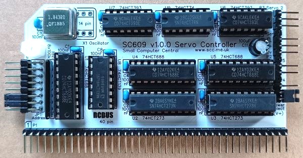
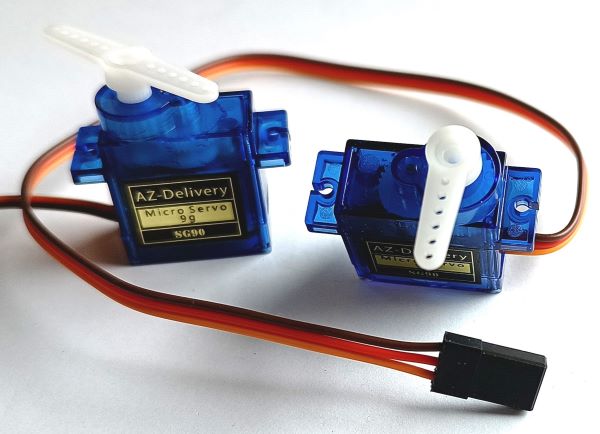
SC609 is a two channel servo controller module for the 40-pin RCBus.
- SC609 – Assembly guide
- SC609 – Compatibility
- SC609 – Parts list
- SC609 – Printed circuit board
- SC609 – User guide
- SC600 series information
- SC600 series support
Downloads
- SC609, v1.0, Kit contents sheet (PDF)
- SC609, v1.0, Schematic (PDF)
- SC609, v1.0, PCB design files (OSHWLab)
- SC609, v1.0, Gerber files (ZIP)
Errata
Nothing known
Suppliers
| Kits | Website | From | Currency |
| Small Computers Direct | SCDirect | UK | GBP |
| Stephen C Cousins | Tindie | UK | USD |
| Small Computer Central | Lectronz | UK | Euro/USD |
| PCBs | Website | From | Currency |
| Small Computers Direct | SCDirect | UK | GBP |
| Stephen C Cousins | Tindie | UK | USD |
| Small Computer Central | Lectronz | UK | Euro/USD |
| Assembled and Tested | Website | From | Currency |
| Not available | |||
| Components | |||
| See parts list |
Tindie does not collect VAT for EU countries
Lectronz does collect EU VAT for orders up to 150 EUR
10 REM Servo demo program
20 FOR Z=1 TO 30
21 NEXT Z
30 IF A<115 OR A>230 THEN A=115
40 IF B<115 OR B>230 THEN B=230
50 OUT 6,A
60 OUT 7,B
70 A=A+1
80 B=B-2
90 GOTO 20
Demonstration Video (MP4, 20MB)
Parts List
| Reference | Qty | Component |
| PCB | 1 | SC609, v1.0, PCB |
| C1 to C10 | 10 | Capacitor, ceramic, 100 nF |
| C11 | 1 | Capacitor, electrolytic, 100 µF |
| JP1 | 1 | Header, male, 2 x 8 pin, angled (or straight to avoid extending beyond the PCB) |
| Jumper | 8 | Jumper shunt |
| P1 | 1 | Header, male, 2 row x 40 pin, angled |
| P2+3+4+5 | 1 | Header, male, 1 x 14 pin, angled |
| RN1 | 1 | Resistor network, 8x100k, SIL, 9-pin |
| Screw (for spacer) | 1 | Machine screw, 6mm, M3 |
| Spacer | 1 | Spacer, 10mm, M3, nylon |
| U1, U4, U5 | 3 | 74HCT688 |
| U2, U3 | 2 | 74HCT273 |
| U6, 7 | 2 | 74HCT393 |
| U8 | 1 | 74HCT139 or 74AHCT139 |
| U9 | 1 | 74HCT74 |
| X1 | 1 | Oscillator 1.8432 MHz |
| IC socket 20-pin U1 to U5 | 5 | Socket, DIP, 20-pin |
| IC socket 16-pin U8 | 1 | Socket, DIP, 16-pin |
| IC socket 14-pin U6, U7, U9, X1 | 4 | Socket, DIP, 14-pin |
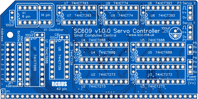
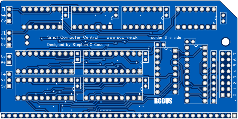
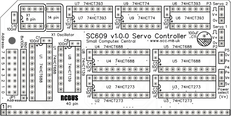
Printed Circuit Board
User Guide
SC609 is a two channel servo controller. It has tight address decoding and easy access with a single OUT instruction to set each servo position.
The address decoding is such that one module takes only two I/O addresses (one for each servo channel). Only writes to those addresses are decoded, so those addresses could be allocated to another device that only has a read function. Many of these modules can be installed in a single system as long as there are no address conflicts.
The output of each channel is set by writing a value from 0 to 255 decimal to the port address of the servo channel. A value of zero turns the pulses off, leaving the output signal at a steady low level. A value of 1 produces the most narrow pulse and 255 the most wide pulse.
Typically, a servo requires a pulse between 1 ms and 2ms. The pulse needs to be repeated about 50 times a second. If no pulse is detected the servo will not move. With a 1.8432 MHz oscillator fitted, a 1 ms pulse is produced when a value of 115 is written to the servo port and a 2 ms pulse is produced by the value 230. The pulses are repeated every 17.8 ms (56.25 Hz).
These figures are derived from the following:
The oscillator is divided by 16 to produce the clock for an 8 bit ripple counter. After 256 clock pulses the ripple counter resets to zero. The rate of counter resets is then divided by 8 to give the repeat frequency.
- Ripple counter clock = 1.8432 MHz / 16 = 115200 Hz
- Ripple counter reset frequency = 115200 / 256 = 450 Hz
- Pulse repeat frequency = 450 / 8 = 56.25 Hz
Examples
If the base I/O address is set to 6, then to set the value of the servo pulse width you need to write the value to I/O address 6. Servo #2 width is set at I/O address 7.
To set the width of servo #1 channel to 200 (decimal) in BASIC:
OUT 6, 200
To set the width of servo #1 channel to 200 (decimal) in assembler:
LD A, $C8
OUT (6), A
Input/output port functions
| RCBus I/O Address | Read | Write |
| Configurable *1 base address | n/a | Write servo value |
- The RCBus I/O address should be set to any even address. Typically, this might be 0x06 (6 decimal). Many of these modules can be included in a single system as long as there are no address conflicts.
Jumper options
| Jumper | Function |
| JP1 | Set SC609’s RCBus I/O address |
| P4 | Set servo power source (typically 5 volts) P4.1-2 Power from computer’s 5 volt supply P4.2-3 Power from external source (P5) While the option is available to power the servo(s) from the computer’s 5 volt supply it is highly recommended that an external supply be used due to noise and loading issues |
Frequencies
The following table gives the frequencies and timings for a range of oscillator frequencies.
| JP 2 position | Oscillator 1.8432 MHz | Oscillator 2.000 MHz | Oscillator 1.024 MHz |
| Oscillator frequency | 1843200 Hz | 2000000 Hz | 1024000 Hz |
| Ripple counter clock | 115200 Hz | 125000 Hz | 64000 Hz |
| Ripple counter reset rate | 450 Hz | 488.28 Hz | 250 Hz |
| Pulse repeat frequency | 56.25 Hz | 61.04 Hz | 31.25 Hz |
| Pulse repeat time | 17.78 ms | 16.38 ms | 32.00 ms |
| 1 ms pulse width value | 115 | 125 | 64 |
| 2 ms pulse width value | 230 | 250 | 128 |
| 1.5 ms (mid position) | 173 | 188 | 96 |
Assembly Guide
Below is the suggested order of assembly. A general guide to assembling circuit boards can be found here.
- Decoupling capacitors C1 to C10 (100 nF)
These can be fitted either way around - Header pins P2 + P3 + P4 + P5 (1 row x 14 pin, angled)
This can be fitted as a single strip if a few pins are removed - Bus header P1 (1 row x 40 pin, angled)
Make sure the pins are parallel to the PCB so that the board is vertical when it is fitted into a backplane socket - Sockets for U1 to U9
Fit such that the notch in the socket matches the curve in the outline on the PCB silkscreen - Socket for X1 (optional, not recommended)
Not recommended as the oscillator is quite large and could touch other modules - Resistor network RN1 (8 x 100k)
This must be fitted the correct way around whereby the dot on the component matches the dot on the PCB silkscreen - Header pins JP1 (2 row x 8 pin, angled or straight)
- Capacitor C11 (100 uF)
This must be fitted the correct way around, as described here - Fit oscillator X1 (1.8432 MHz)
- Insert the integrated circuits into their sockets
Make sure the notch in the component is at the end indicated by the notch in the socket and the curve on the PCB silkscreen - Fit the nylon spacer in the mounting hole
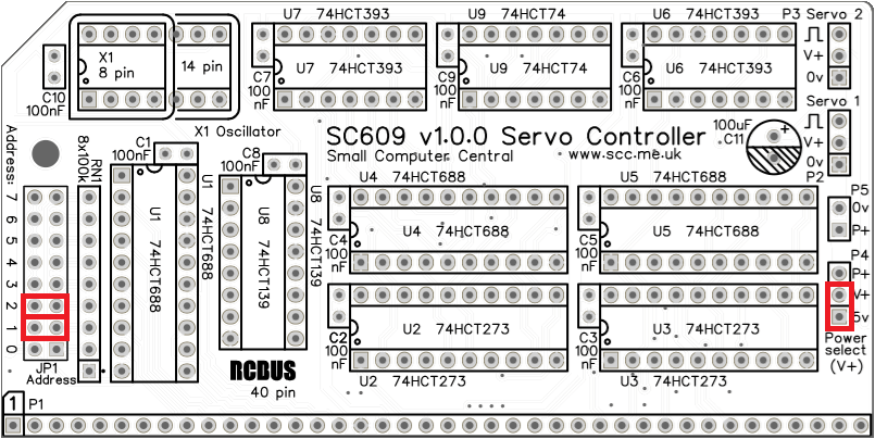
Fit jumper shunts in the positions shown below. All other jumpers are optional and should only be fitted if the feature is required.
Compatibility
This module conforms to the RCBus specification v1.0 for RCBus-2014 (40-pin bus) and RCBus-Z80 (40-pin bus).
The RCBus specification includes RCBus-2014 (both RC2014 standard 40-pin bus and RC2014 enhanced 60-pin bus) and also the full 80-pin RCBus. The 80-pin RCBus provides support for advanced Z80 features, such as the interrupt daisy-chain, as well as support for other processor families.
The table below indicates electrical compatibility with each backplane type (40, 60 and 80 pin)

| Backplane | ? | Compatibility notes |
| RCBus 80-pin |  | Fully supported |
| RCBus 60-pin (RC2014 enhanced) | | Fully supported |
| RCBus 40-pin (RC2014 standard) | | Fully supported |
Notes
- This product is designed for hobby use and is not suitable for industrial, commercial, or safety-critical applications.
- The product contains small parts and is not suitable for young children.
