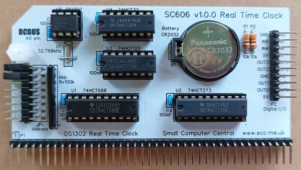
SC606 is a DS1302 based real time clock designed for the 40-pin RCBus.
- SC606 – Assembly guide
- SC606 – Compatibility
- SC606 – Parts list
- SC606 – Printed circuit board
- SC606 – User guide
- SC600 series information
- SC600 series support
Downloads
- SC606, v1.0, Kit contents sheet (PDF)
- SC606, v1.0, Schematic (PDF)
- SC606, v1.0, PCB design files (OSHWLab)
- SC606, v1.0, Gerber files (ZIP)
Errata
- Nothing known
Suppliers
| Kits | Website | From | Currency |
| Small Computers Direct | SCDirect | UK | GBP |
| Stephen C Cousins | Tindie | UK | USD |
| Small Computer Central | Lectronz | UK | Euro/USD |
| PCBs | Website | From | Currency |
| Small Computers Direct | SCDirect | UK | GBP |
| Stephen C Cousins | Tindie | UK | USD |
| Small Computer Central | Lectronz | UK | Euro/USD |
| Assembled and Tested | Website | From | Currency |
| Not available | |||
| Components | |||
| See parts list |
Tindie does not collect VAT for EU countries
Lectronz does collect EU VAT for orders up to 150 EUR
Parts List
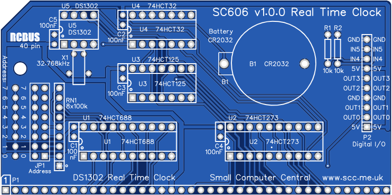
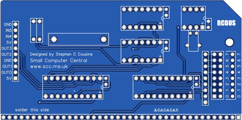
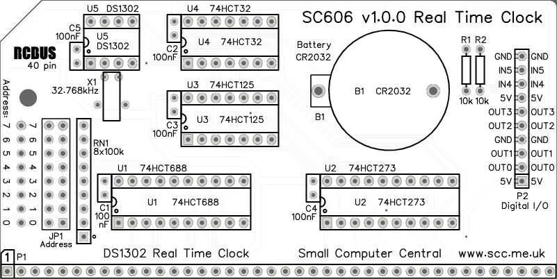
Printed Circuit Board
User Guide
SC606 includes a real time clock based on a DS1302+ integrated circuit. Several spare I/O bits are also available for user functions. Support for the real time clock is included in RomWBW but not in plain CP/M 2.2 or in the Small Computer Monitor.
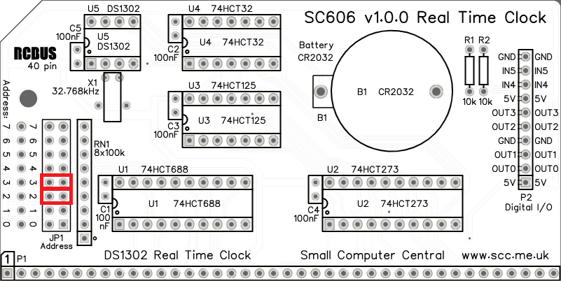
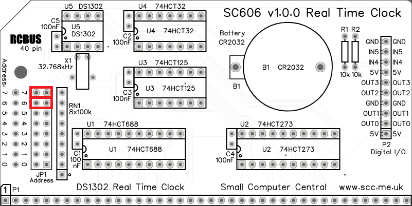
The module’s I/O address is set with jumpers (JP1). Check the requirements of the software you intend to use. Fit a jumper shunt in each position where the corresponding address bit is to be a ‘1’ (high).
Header pins P2 provide access to spare I/O bits not used for the real time clock. The input bits can be used without restrictions but outputting values to the output bits must be done with care as the port is shared with the real time clock output bits.
Input/output port functions
| RCBus I/O Address | Read | Write |
| Configurable *1 base address | Inputs | Outputs |
| Bit 0 | RTC serial data | Output bit 0 |
| Bit 1 | Undefined | Output bit 1 |
| Bit 2 | Undefined | Output bit 2 |
| Bit 3 | Undefined | Output bit 3 |
| Bit 4 | Input bit 4 | RTC chip enable (lo) |
| Bit 5 | Input bit 5 | RTC write enable (lo) |
| Bit 6 | Undefined | RTC serial clock |
| Bit 7 | Undefined | RTC serial data |
The RCBus I/O base address should be set to match the software you are using. Typically, this is 0x0C or 0xC0.
Jumper options
| Jumper | Function |
| JP1 | Set module’s RCBus I/O address |
Connectors
| Connector | Function |
| P1 | RCBus connector |
| P2 | Digital I/O Pin 1 = 5 volts output Pin 2 = Output bit 0 Pin 3 = Output bit 1 Pin 4 = Ground (0 volts) Pin 5 = Output bit 2 Pin 6 = Output bit 3 Pin 7 = 5 volts output Pin 8 = Input bit 4 Pin 9 = Inpit bit 5 Pin 10 = Ground (0 volts) |
Assembly Guide
Below is the suggested order of assembly. A general guide to assembling circuit boards can be found here.
- Resistors R1 and R2
These can be fitted either way around - Crystal X1
These can be fitted either way around
The crystal can be held firmly in place with a piece of wire, such as an off-cut of resistor or capacitor leg, fitted through the holes provided - Decoupling capacitors C1 to C5 (100nF)
These can be fitted either way around - Bus header P1 (1 row x 40 pin, angled)
Make sure the pins are parallel to the PCB so that the board is vertical when it is fitted into a backplane socket - Header pins P2 (1 row x 10 pin, angled)
- Sockets for U1 to U5
Fit such that the notch in the socket matches the curve in the outline on the PCB silkscreen - Resistor networks RN1
These must be fitted the correct way around whereby the dot on the component matches the dot on the PCB silkscreen - Header pins JP1
- Battery holder B1
- Insert the integrated circuits into their sockets
Make sure the notch in the component is at the end indicated by the notch in the socket and the curve on the PCB silkscreen - Fit a CR2032 battery into the battery holder
The module can be used with or without a battery but without the battery the time is not maintained when the main power is off - Fit the nylon spacer in the mounting hole
Fit jumper shunts to select the required I/O address. The two most commonly used addresses are illustrated below. Check the needs of the software you intend using.
Compatibility
This module conforms to the RCBus specification v1.0 for RCBus-2014 (40-pin bus) and RCBus-Z80 (40-pin bus).
The RCBus specification includes RCBus-2014 (both RC2014 standard 40-pin bus and RC2014 enhanced 60-pin bus) and also the full 80-pin RCBus. The 80-pin RCBus provides support for advanced Z80 features, such as the interrupt daisy-chain, as well as support for other processor families.
The table below indicates electrical compatibility with each backplane type (40, 60 and 80 pin)

| Backplane | ? | Compatibility notes |
| RCBus 80-pin |  | Fully supported |
| RCBus 60-pin (RC2014 enhanced) | | Fully supported |
| RCBus 40-pin (RC2014 standard) | | Fully supported |
Notes
- This product is designed for hobby use and is not suitable for industrial, commercial, or safety-critical applications.
- The product contains small parts and is not suitable for young children.
- RomWBW is copyright Wayne Warthen and has been provided free of charge with his permission.
- RC2014 is a trademark of RFC2795 Ltd.
