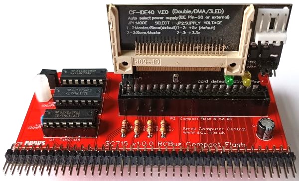
SC715 is a Compact Flash module designed for the RCBus.
There is an alternative design: SC729
- SC715 – Assembly guide
- SC715 – Compatibility
- SC715 – Parts list
- SC715 – Printed circuit board
- SC715 – User guide
- SC700 series information
- SC700 series support
Downloads
- SC715, v1.0, Kit contents sheet (PDF)
- SC715, v1.0, Schematic (PDF)
- SC715, v1.0, PCB design files (OSHWLab)
- SC715, v1.0, Gerber files (ZIP)
Errata
See notes about the Compact Flash adapter.
Suppliers
| Kits | Website | From | Currency |
| Small Computers Direct | SCDirect | UK | GBP |
| Stephen C Cousins | Tindie | UK | USD |
| Small Computer Central | Lectronz | UK | Euro/USD |
| PCBs | Website | From | Currency |
| Small Computers Direct | SCDirect | UK | GBP |
| Stephen C Cousins | Tindie | UK | USD |
| Small Computer Central | Lectronz | UK | Euro/USD |
| Assembled and Tested | Website | From | Currency |
| Not available | |||
| Components | |||
| See parts list |
Tindie does not collect VAT for EU countries
Lectronz does collect EU VAT for orders up to 150 EUR
Parts List
| Reference | Qty | Component |
| PCB | 1 | SC715, v1.0, PCB |
| C1 to C3 | 3 | Capacitor, ceramic, 100 nF |
| C4 | 1 | Capacitor, electrolytic, 100 µF |
| LED1 | 1 | LED, green, 3mm, angled |
| P1 | 1 | Header, male, 2 row x 40 pin, angled |
| P2 | 1 | Box header, 2 x 20 pin, straight *, or Header, male, 2 x 20 pin, straight * included in the kit |
| R1 to R3 | 3 | Resistor, 4k7, 0.25W |
| R4 | 1 | Resistor, 1k, 0.25W |
| Screw (for spacer) | 3 | Machine screw, 6mm, M3 |
| Spacer | 3 | Spacer, 10mm, M3, nylon |
| U1 | 1 | 74HCT138 |
| U2 | 1 | 74HCT32 |
| U3 | 1 | 74HCT74 |
| IC socket 16-pin U1 | 1 | Socket, DIP, 16-pin |
| IC socket 14-pin U2 and U3 | 2 | Socket, DIP, 14-pin |
| Adapter | 1 | Compact Flash adapter |
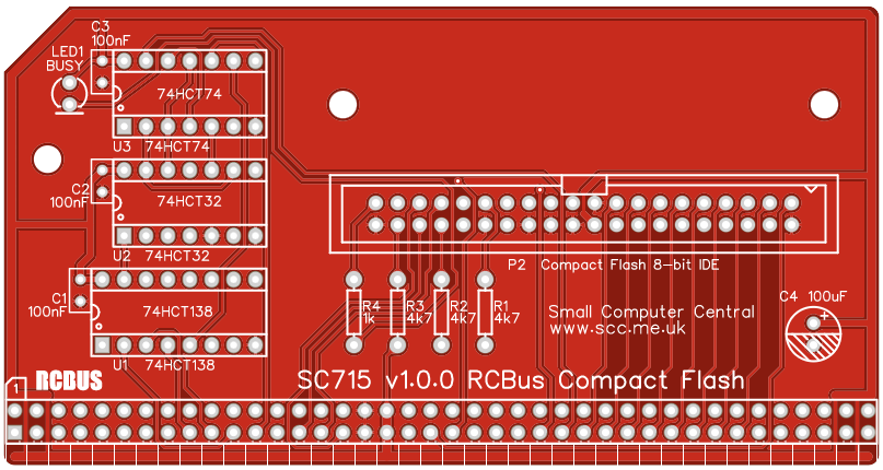
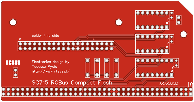
Printed Circuit Board
User Guide
SC715 is a Compact Flash Card interface for RCBus. It uses Tadeusz Pycio’s design to correct the timing between the Z80 CPU and the Compact Flash card.
The module is designed to be mounted either horizontally at the end of a modular backplane, as illustrated below.
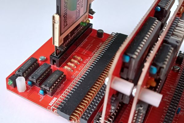
Alternatively, it can be mounted vertically.
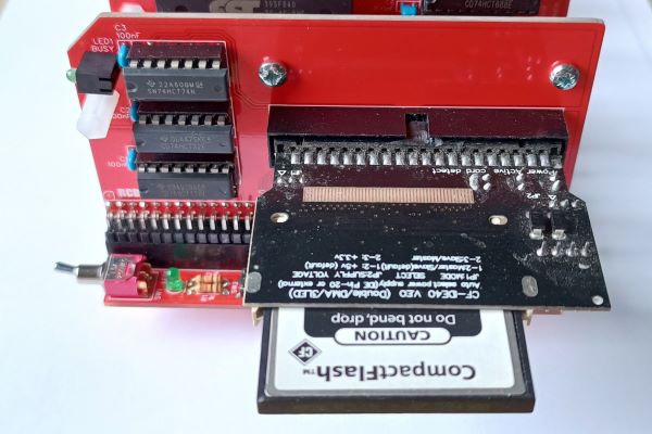
The LED indicates Compact Flash card activity, both read or write.
The Compact Flash card capacity is not critical, but it should be noted that plain CP/M 2.2 can only access the first 128MB of the card. RomWBW can access up to 2GB. Any space above these limits can not be accessed by the retro computer. High capacity, more modern, high speed cards are best avoided as they are more likely to cause noise issues on the bus.
Input/output port functions
| I/O Address | Read | Write |
| 0x10 to 0x17 | CF card | CF card |
Jumper options
| Jumper | Function |
| none |
Assembly Guide
Below is the suggested order of assembly. A general guide to assembling circuit boards can be found here.
See notes about the Compact Flash adapter.
- Resistors R1 to R4
These can be fitted either way around - Decoupling capacitors C1, C2 and C3
These can be fitted either way around - Sockets for U1, U2 and U3
Fit such that the notch in the socket matches the curve in the outline on the PCB silkscreen - Bus header P1
Make sure the pins are parallel to the PCB so that the board is vertical when it is fitted into a backplane socket - Light emitting diode LED1
The angled LEDs in the kit only fit one way around, but standard LEDs need to have the short lead in the hole marked with a flat line, as described here - Capacitor C4
This must be fitted the correct way around, as described here - Box header P2
The kit includes a box header, but straight header pins could be used instead. Ensure the orientation matches the outline on the PCB’s silkscreen. - Insert the integrated circuits into their sockets
Make sure the notch in the component is at the end indicated by the notch in the socket and the curve on the PCB silkscreen - Fit the nylon spacers in the mounting holes
The two by the Compact Flash socket are designed to be fitted on the solder side of the PCB so that the module is supported when connected horizontally to a modular backplane, such as SC701, SC702, SC709 or SC710. They are not needed if the module is mounted vertically.
Compatibility
This module conforms to the RCBus specification v1.0 for RCBus-2014 and RCBus-Z80.
The RCBus specification includes RCBus-2014 (both RC2014 standard 40-pin bus and RC2014 enhanced 60-pin bus) and also the full 80-pin RCBus. The 80-pin RCBus provides support for advanced Z80 features, such as the interrupt daisy-chain, as well as support for other processor families.
The table below indicates electrical compatibility with each backplane type (40, 60 and 80 pin)

| Backplane | ? | Compatibility notes |
| RCBus 80-pin |  | Fully supported |
| RCBus 60-pin (RC2014 enhanced) | | Fully supported |
| RCBus 40-pin (RC2014 standard) | | Fully supported |
Notes
- This product is designed for hobby use and is not suitable for industrial, commercial, or safety-critical applications.
- The product contains small parts and is not suitable for young children.
- The Compact Flash interface circuit has been designed by Tadeusz Pycio and reproduced with his permission.
