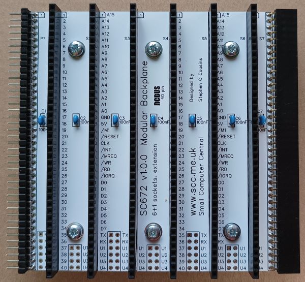
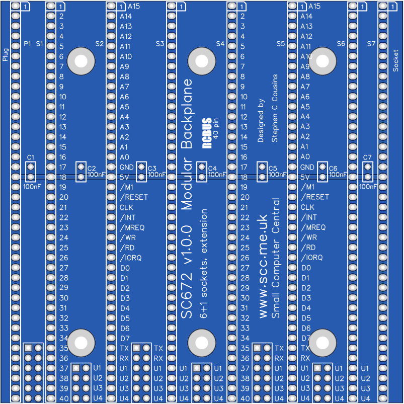
SC672 is a 40-pin RCBus modular backplane with 6 vertical bus sockets, 1 horizontal bus socket, and one horizontal bus plug.
- SC672 – Assembly guide
- SC672 – Compatibility
- SC672 – Interrupt daisy chain
- SC672 – Parts list
- SC672 – Printed circuit board
- SC672 – User guide
- SC600 series information
- SC600 series support
Downloads
- SC672, v1.0, Kit contents sheet (PDF)
- SC672, v1.0, Schematic (PDF)
- SC672, v1.0, PCB design files (OSHWLab)
- SC672, v1.0, Gerber files (ZIP)
Warnings
Assembly: Ensure the bus sockets are pressed firmly against the PCB alone their entire length
Errata
Nothing known
Suppliers
| Kits | Website | From | Currency |
| Small Computers Direct | SCDirect | UK | GBP |
| Stephen C Cousins | Tindie | UK | USD |
| Small Computer Central | Lectronz | UK | Euro/USD |
| PCBs | Website | From | Currency |
| Small Computers Direct | SCDirect | UK | GBP |
| Stephen C Cousins | Tindie | UK | USD |
| Small Computer Central | Lectronz | UK | Euro/USD |
| Assembled and Tested | Website | From | Currency |
| Not available | |||
| Components | |||
| See parts list |
Tindie does not collect VAT for EU countries
Lectronz does collect EU VAT for orders up to 150 EUR
Parts List
| Reference | Qty | Component |
| PCB | 1 | SC672, v1.0, PCB |
| C1 to C7 | 7 | Capacitor, ceramic, 100 nF |
| JP1, 3 and 5 | 3 | Header, male, 2 row x 6 pin, straight Not included in kit Thin tracks link these options |
| JP2, 4 and 6 | 3 | Header, male, 2 row x 4 pin, straight Not included in kit Thin tracks link these options |
| P1 | 1 | Header, male, 2 row x 40 pin, angled (type B profile) or Header, male, 2 row x 40 pin, angled (the second row of pins needs to be removed) |
| S1 to S6 | 6 | Header, female, 1 row x 40 pin, straight |
| S7 | 1 | Header, female, 1 row x 40 pin, angled |
| Spacer | 6 | Spacer, 10mm, M3, nylon |
| Screw (for spacer) | 6 | Machine screw, 6mm, M3 |
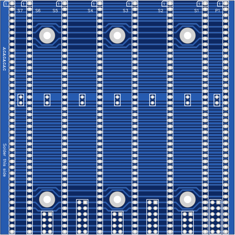
Printed Circuit Board
User Guide
This backplane section can be used as an extension to other backplane sections or it can be used as the only backplane in the system.
Input/output port functions
| I/O Address | Read | Write |
| none | n/a | n/a |
Jumper options
| Jumper | Function |
| JP 1, 3, 5 | JPx.1 Connect P37 signal between bus sockets JPx.2 Connect P38 signal between bus sockets* JPx.3 Connect P39 signal between bus sockets* * See daisy chain details below |
| JP 1, 3, 5 | JPx.1 Connect TX signal between bus sockets JPx.2 Connect RX signal between bus sockets JPx.3 Connect U1 signal between bus sockets JPx.4 Connect U2 signal between bus sockets JPx.5 Connect U3 signal between bus sockets JPx.6 Connect U4 signal between bus sockets Thin tracks on the under side of the PCB link these jumper positions, thus signals TX, RX, U1, U2, U3 and U4 are connected to each backplane socket |
| JP2, 4, 6 | JPx.1 Connect U1 signal between bus sockets JPx.2 Connect U2 signal between bus sockets JPx.3 Connect U3 signal between bus sockets JPx.4 Connect U4 signal between bus sockets Thin tracks on the under side of the PCB link these jumper positions, thus signals U1, U2, U3 and U4 are connected to each backplane socket |
JP1 to JP6 allow some signals to be isolated between bus sockets. This can be helpful if there are several modules that use these signals for different functions.
Thin tracks on the under side of the PCB link these jumper positions, thus signals TX (pin 35), RX (pin 36), U1 (pin 37), U2 (pin 38), U3 (pin 39) and U4 (pin 40) are connected to each backplane socket. To isolate any of these signals it is necessary to cut the required thin track. Most users will not need to do this. It is only more complex set ups that need any of these signals isolated.
Bus signals U1 to U4 have no specified function on the original RC2014 bus and were known as SPARE or USER signals.
Assembly Guide
Below is the suggested order of assembly. A general guide to assembling circuit boards can be found here.
- Bus socket S7
- Decoupling capacitors C1 to C7
These can be fitted either way around - Header pins P1
- Bus sockets S1 to S6
Ensure the bus sockets are pressed firmly against the PCB along their entire length
Compatibility
This backplane conforms to the RCBus specification v1.0 for 40-pin systems. Namely, RCBus-2014 standard bus.
The RCBus specification includes RCBus-2014 (both RC2014 standard 40-pin bus and RC2014 enhanced 60-pin bus) and also the full 80-pin RCBus. The 80-pin RCBus provides support for advanced Z80 features, such as the interrupt daisy-chain, as well as support for other processor families.
Notes
- This product is designed for hobby use and is not suitable for industrial, commercial, or safety-critical applications.
- The product contains small parts and is not suitable for young children.
