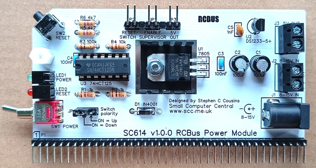
SC614 is a power supply module for RCBus.
- SC614 – Assembly guide
- SC614 – Compatibility
- SC614 – Parts list
- SC614 – Printed circuit board
- SC614 – User guide
- SC600 series information
- SC600 series support
Downloads
- SC614, v1.0, Kit contents sheet (PDF)
- SC614, v1.0, Schematic (PDF)
- SC614, v1.0, PCB design files (OSHWLab)
- SC614, v1.0, Gerber files (ZIP)
Errata
Nothing known
Suppliers
| Kits | Website | From | Currency |
| Small Computers Direct | SCDirect | UK | GBP |
| Stephen C Cousins | Tindie | UK | USD |
| Small Computer Central | Lectronz | UK | Euro/USD |
| PCBs | Website | From | Currency |
| Small Computers Direct | SCDirect | UK | GBP |
| Stephen C Cousins | Tindie | UK | USD |
| Small Computer Central | Lectronz | UK | Euro/USD |
| Assembled and Tested | Website | From | Currency |
| Not available | |||
| Components | |||
| See parts list |
Tindie does not collect VAT for EU countries
Lectronz does collect EU VAT for orders up to 150 EUR
Parts List
| Reference | Qty | Component |
| PCB | 1 | SC614, v1.0, PCB |
| C1 and C2 | 2 | Capacitor, electrolytic 100 µF |
| C3 and C4 | 2 | Capacitor, ceramic, 100 nF |
| C5 | 1 | Capacitor, ceramic, 1 nF |
| D1 | 1 | Diode, 1N4001 |
| J1 | 1 | Socket, power, barrel, 2.1mm |
| J2 and J3 | 2 | Screw terminal, 2 way, 5mm pitch |
| JP1, P2, P3 | 3 | Header, male, 1 row x 2 pin, angled or 8 pin strip with 2 pins removed |
| JP2 | 1 | Wire link (eg. resistor offcut), or Header, male, 1 row x 3 pin, straight |
| Jumper | 2 | Jumper shunt |
| LED1 | 1 | LED, green, 3mm, angled |
| LED2 | 1 | LED, red, 3mm, angled |
| P1 | 1 | Header, male, 1 row x 40 pin, angled |
| P2 and P3 | see JP1 | |
| R1 and R2 | 2 | Resistor, 1k, 0.25W |
| R3 | 1 | Resistor, 100k, 0.25W |
| R4 | 1 | Resistor, 10k, 0.25W |
| R5 and R6 | 2 | Resistor, 4k7, 0.25W |
| SW1 | 1 | Switch, toggle, sub-miniature, SPDT |
| SW2 | 1 | Switch, tactile button, angled |
| Screw (for spacer) | 1 | Machine screw, 6mm, M3 |
| Spacer | 1 | Spacer, 10mm, M3, nylon |
| Nut (for U1) | 1 | Nut, M3.5 |
| Bold (for U1) | 1 | Bolt, M3.5, 10mm, pan head |
| Heatsink (for U1) | 1 | Heatsink TO-220, 19x20x9mm |
| U1 | 1 | 7805 regulator, 5V, 1A |
| U2 | 1 | DS1233-5+ supervisor |
| U3 | 1 | 74HCT125 |
| IC socket 14-pin U3 | 1 | 14-pin PDIP socket |
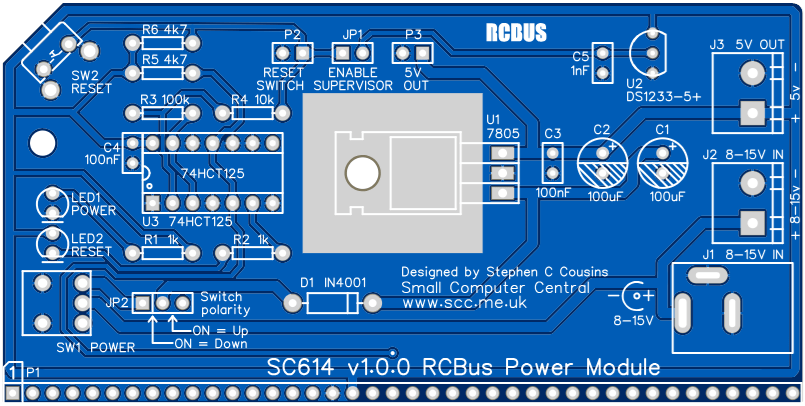
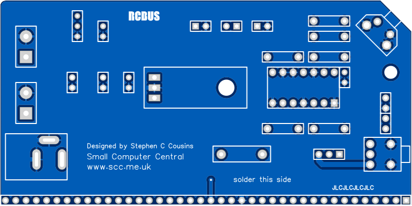
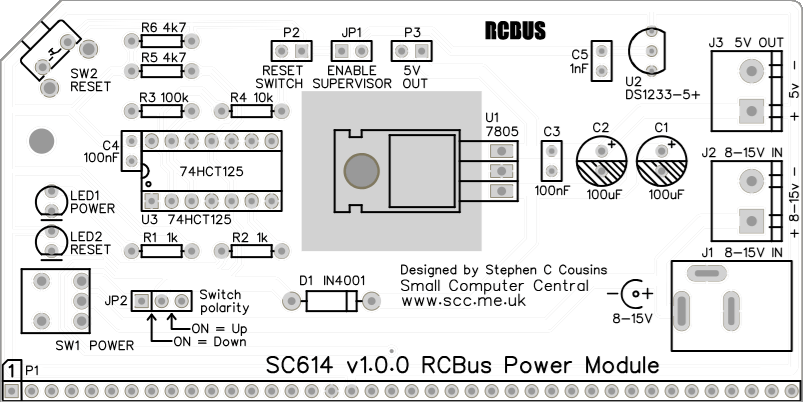
Printed Circuit Board
User Guide
This module provides a regulated 5-volt supply to the backplane. Voltage input is between 8 and 15 volts D.C. at a maximum of 1 ampere. The regulator will get warm in normal use. The higher the input voltage and the greater the current load, the hotter it will get. The input can be connected to either J1 (centre positive) or the screw terminal J2.
The 5-volt output is connected to the backplane and is also available at screw terminal J3 and header pins P3.
The system reset signal is generated at power up, upon pressing switch SW2, or with an external switch connected to P2. The power up reset is generated by the voltage supervisor U2. The supervisor will also hold the system in reset if the 5-volt supply drops below about 4.75 volts. In addition, the supervisor cleans up the reset signal generated with the reset button.
The system should only have one enabled voltage supervisor. If there is another one in the system, one of them needs to be disabled. The circuit on this module is likely to be the best one, so ideally keep this one enabled and disable any others. To enable the supervisor on this module, fit a jumper shunt to header pins JP1.
Input/output port functions
| RCBus I/O Address | Read | Write |
| none | n/a | n/a |
Jumper options
| Jumper | Function |
| JP 1 | Enable the voltage supervisor Only one supervisor should be enabled in a system so it may be necessary to disable (isolate) one of them |
| JP 2 | Select the polarity of the on/off switch, either UP for ON or DOWN for ON |
Connectors
| Connector | Function |
| J 1 | Barrel socket, power supply input, 8 to 15 volts D.C. centre positive, maximum current 1 ampere |
| J 2 | Screw terminal, power supply input, 8 to 15 volts D.C. centre positive, maximum current 1 ampere |
| J 3 | Screw terminal, 5-volt output, maximum current 1 ampere |
| P 1 | RCBus connector |
| P 2 | Header pins, optional external reset switch |
| P 3 | Header pins, 5-volt output, maximum current 1 ampere |
Assembly Guide
Below is the suggested order of assembly. A general guide to assembling circuit boards can be found here.
- Resistors R1 to R6
These can be fitted either way around - Diode D1 (1N4001)
This must be fitted the correct way around, with the band on the diode matching the marking on the PCB - Header pins P1 (1 row x 40 pin, angled)
Make sure the pins are parallel to the PCB so that the board is vertical when it is fitted into a backplane socket - Header pins JP1, P2 and P3 (1 row x 8 pin, angled)
P2, JP1 and P3 can be a single strip with two pins removed - Socket for U3 (14-pin)
Ensure the notch in the socket matches the marking on the PCB - Capacitor C5 (1 nF)
This can be fitted either way around - Capacitors C3 and C4 (100 nF)
These can be fitted either way around - Capacitors C1 and C2 (100 uF)
This must be fitted the correct way around, as described here - Switch SW1 (toggle switch)
- LED1 and LED2
The angled LEDs in the kit only fit one way around, but standard LEDs need to have the short lead in the hole marked with a flat line, as described here - Switch SW2 (tactile botton)
- Barrel power socket J1
- Screw terminals J2 and J3
- Regulator U1 and heatsink (7805 regulator)
- Header pins JP2 (1 row x 3 pin, straight)
- Voltage supervisor U2 (DS1233-5+)
Carefully bend the legs to match the hole spacing on the PCB and ensure the orientation matches the markings on the PCB - Fit IC’s U3 into its socket (74HCT125)
Ensure the notch in the IC matches the PCB and IC socket - Fit jumper shunts to JP1 (if required) and JP2
JP1 is only required if the system doesn’t already have a voltage supervisor
JP2 has two possible positions depending on your preference for the on/off switch polarity (ie. UP=ON or DOWN=ON) - Fit the nylon spacer in the mounting hole
Compatibility
This module conforms fully to the RCBus specification v1.0 for the 40-pin RCBus.
It is fully functional on backplanes with 40 or 80 pin sockets.
The RCBus specification includes RCBus-2014 (both RC2014 standard 40-pin bus and RC2014 enhanced 60-pin bus) and also the full 80-pin RCBus. The 80-pin RCBus provides support for advanced Z80 features, such as the interrupt daisy-chain, as well as support for other processor families.
The table below indicates electrical compatibility with each backplane type (40, 60 and 80 pin)

| Backplane | ? | Compatibility notes |
| RCBus 80-pin |  | Fully supported |
| RCBus 60-pin (RC2014 enhanced) | | Fully supported |
| RCBus 40-pin (RC2014 standard) | | Fully supported |
Notes
- This product is designed for hobby use and is not suitable for industrial, commercial, or safety-critical applications.
- The product contains small parts and is not suitable for young children.
