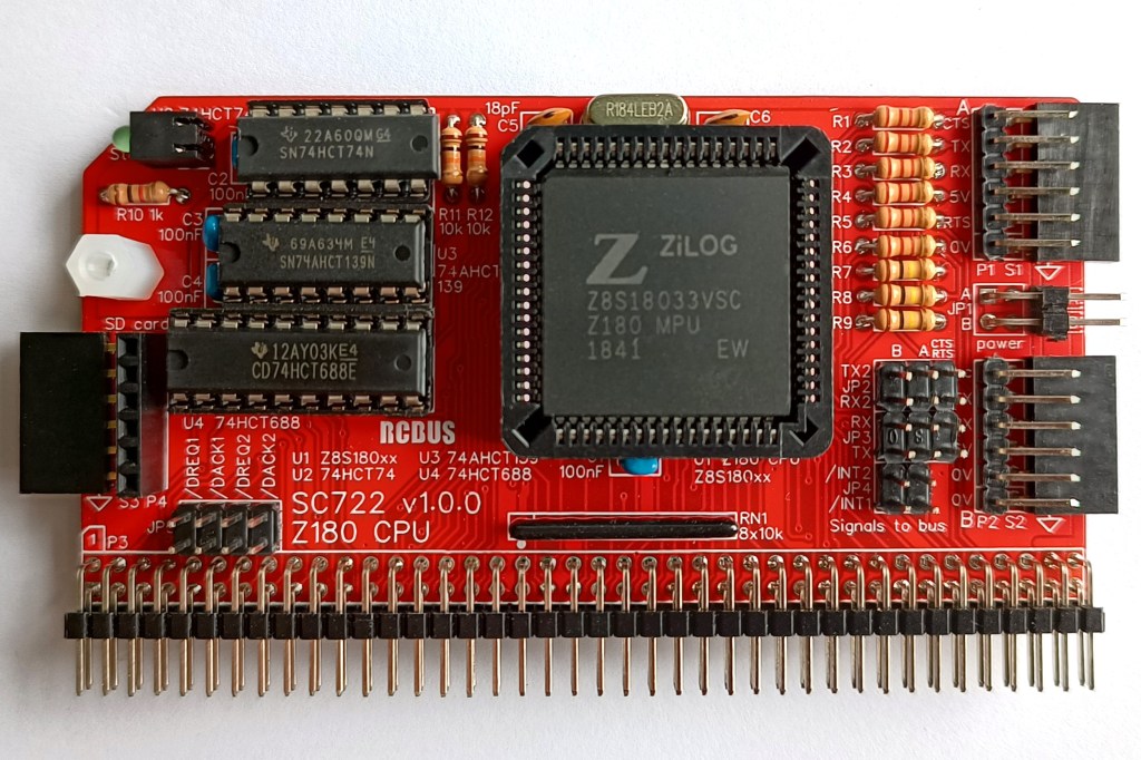
SC722 is a Z180 CPU module designed for the 80-pin RCBus. It includes two serial ports and an SD card port.
- SC722 – Assembly guide
- SC722 – Compatibility
- SC722 – Firmware: RomWBW_SCZ180_SC700
- SC722 – Firmware: SCM S9
- SC722 – Parts list
- SC722 – Printed circuit board
- SC722 – User guide
- SC700 series information
- SC700 series support
Downloads
- SC722, v1.0, Kit contents sheet (PDF)
- SC722, v1.0, Schematic (PDF)
- SC722, v1.0, PCB design files (OSHWLab)
- SC722, v1.0, Gerber files (ZIP)
Errata
- PCB SC722 v1.0.0 has JP2 labels RX2 and TX2 swapped. Fixed in PCB v1.0.1
Suppliers
| Kits | Website | From | Currency |
| Small Computers Direct | SCDirect | UK | GBP |
| Stephen C Cousins | Tindie | UK | USD |
| Small Computer Central | Lectronz | UK | Euro/USD |
| PCBs | Website | From | Currency |
| Small Computers Direct | SCDirect | UK | GBP |
| Stephen C Cousins | Tindie | UK | USD |
| Small Computer Central | Lectronz | UK | Euro/USD |
| Assembled and Tested | Website | From | Currency |
| Not available | |||
| Components | |||
| See parts list |
Tindie does not collect VAT for EU countries
Lectronz does collect EU VAT for orders up to 150 EUR
Parts List
| Reference | Qty | Component |
| PCB | 1 | SC722, v1.0.x, PCB |
| C1 to C4 | 4 | Capacitor, ceramic, 100 nF |
| C5 and C6 | 1 | Capacitor, ceramic, 18 pF |
| JP1 | 1 | Header, male, 2 row x 2 pin, angled |
| JP2 and JP3 | 2 | Header, male, 2 row x 3 pin, straight |
| JP4 | 1 | Header, male, 2 row x 2 pin, straight |
| JP5 | 1 | Header, male, 2 row x 4 pin, straight |
| Jumper | 12 | Jumper shunt |
| LED1 | 1 | LED, green, 3mm, angled |
| P1 and P2 | 2 | Header, male, 1 row x 6 pin, angled |
| P3 | 1 | Header, male, 2 row x 40 pin, angled |
| P4 | 1 | Header, male, 1 row x 6 pin, angled or Header, female, 1 row x 6 pin, straight |
| R1 to R6 | 6 | Resistor, 2k2, 0.25W |
| R7 to R9 | 3 | Resistor, 100k, 0.25W |
| R10 | 1 | Resistor, 1k, 0.25W |
| R11 and R12 | 2 | Resistor, 10k, 0.25W |
| RN1 | 1 | Resistor network, 8x10k, SIL, 9-pin |
| S1, S2 and S3 | 1 | Header, female, 1 row x 6 pin, angled |
| S3 | 1 | Header, female, 1 row x 6 pin, angled or Header, male, 1 row x 6 pin, angled |
| Screw (for spacer) | 1 | Machine screw, 6mm, M3 |
| Spacer | 1 | Spacer, 10mm, M3, nylon |
| U1 | 1 | Z8S18033VSG (Z180 CPU) or Z8S18033VSC or Z8S18020VSG or Z8S18020VSC |
| U2 | 1 | 74HCT74 |
| U3 | 1 | 74AHCT139 |
| U4 | 1 | 74HCT688 |
| X1 | 1 | Crystal, 18.432 MHz |
| IC socket 68-pin U1 | 1 | 68-pin PLCC socket |
| IC socket 14-pin U2 | 1 | 14-pin PDIP socket |
| IC socket 16-pin U3 | 1 | 16-pin PDIP socket |
| IC socket 20-pin U4 | 1 | 20-pin PDIP socket |
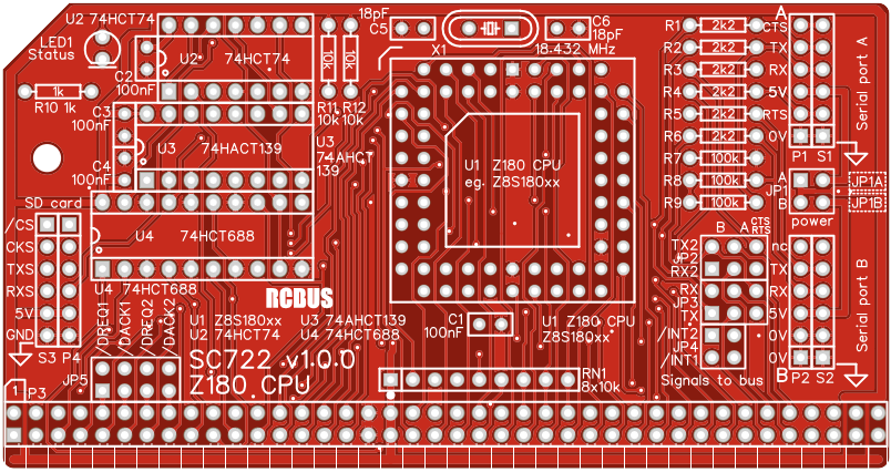
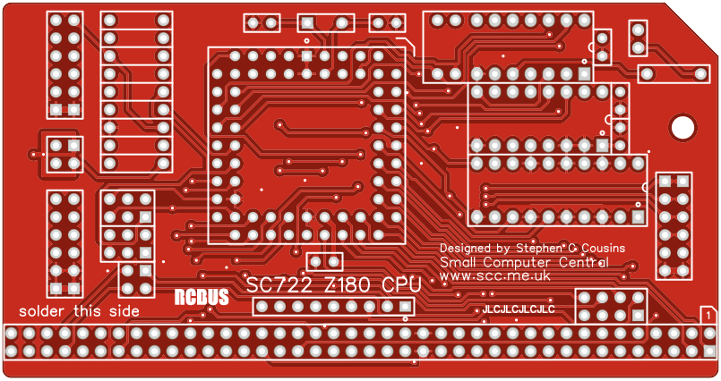
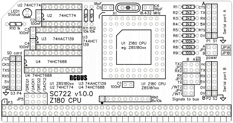
Printed Circuit Board
User Guide
SC722 is a Z180 CPU module designed for the 80-pin RCBus. It includes two serial ports and an SD card port.
The recommended memory module for use with this CPU is SC721, which allows two firmware options to be installed at the same time. This will typically be RomWBW and SCM. RomWBW supports SD cards for storage, but SCM doesn’t.
Both firmware options support the serial ports at 115200 baud, 8 data bits, 1 stop bit, no parity. RTS/CTS flow control is recommended for serial port A. The Z180 CPU does not support RTS/CTS flow control for serial port B .
Jumpers on this module allow a range of signals to be connected to various bus pins, as detailed below. These only need connecting if your system configuration requires them. For example, if you have a terminal module you may need to connect the TX and RX signals from which ever serial port you wish to use.
Jumpers (JP1) allow port to be taken from or supplied to serial devices in ports A or B. Only supply power to the system from one source.
Input/output port functions
| I/O Address | Read | Write |
| 0x0C bit 2 | n/a | SD card chip select (active low) |
| 0x0E bit 0 | n/a | Status LED (active low) |
Jumper options
| Jumper | Function |
| JP1 | Connect 5V power to serial ports JP 1.1-2, Connect 5V power to serial port A JP 1.3-4, Connect 5V power to serial port B The default is no jumper shunts fitted |
| JP2 | Connects serial signals to bus pins TX2 and RX2 JP 2.1-3, Connects port B transmit TXB to bus TX2 JP 2.3-5, Connects port A /RTS to bus TX2 JP 2.2-4, Connects port B receive RXB to bus RX2 JP 2.4-6, Connects port A /CTS to bus RX2 The default is no jumper shunts fitted |
| JP3 | Connects serial signals to bus pins TX and RX JP 3.1-3, Connects port A transmit TXA to bus TX JP 3.3-5, Connects port B transmit TXB to bus TX JP 3.2-4, Connects port A receive RXA to bus RX JP 3.4-6, Connects port B receive RXB to bus RX The default is no jumper shunts fitted |
| JP4 | Connects Z180 interrupt signals to bus pins 37 and 77 JP 4.1-2, Connects Z180 /INT2 signal to bus pin 77 JP 4.3-4, Connects Z180 /INT1 signal to bus pin 37 The default is no jumper shunts fitted |
| JP5 | Connects Z180 DMA signals to bus pins 45 to 48 JP 5.1-2, Connects Z180 /DREQ0 signal to bus pin 45 JP 5.3-4, Connects Z180 /TEND0 signal to bus pin 46 JP 5.5-6, Connects Z180 /DREQ1 signal to bus pin 47 JP 5.7-8, Connects Z180 /TEND1 signal to bus pin 48 The default is no jumper shunts fitted |
Jumper pins JP2, JP3 and JP4 are illustrated below.
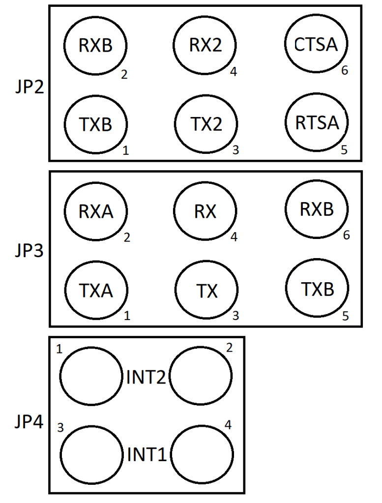
TX and RX are signals to RCBus pins 35 and 36.
TX2 and RX2 are signals to RCBus pins 75 and 76.
TXA and RXA are transmit and receive from SIO port A.
RTSA and CTSA are flow control signals from SIO port A.
TXB and RXB are transmit and receive from SIO port B.
INT1 and INT2 are interrupt signals to the CPU from RCBus pins 37 and 77.


Assembly Guide
Below is the suggested order of assembly. A general guide to assembling circuit boards can be found here.
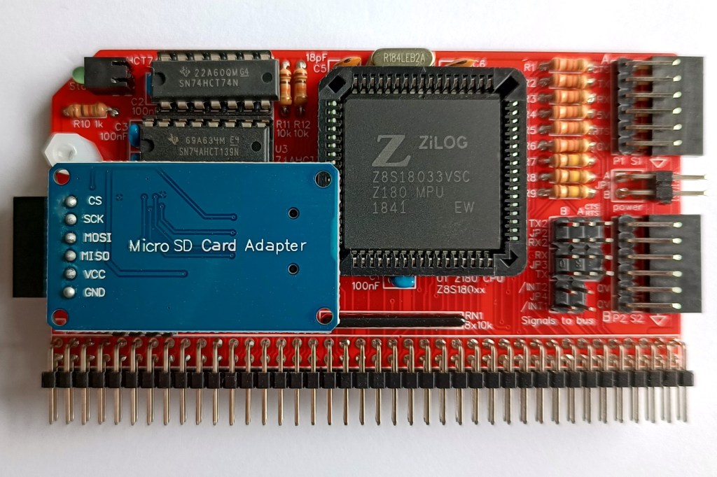
Before starting assembly decide how you want to mount the SD card adapter (assuming you will at some point use one). The adapter can be fitted in any of the ways shown below.
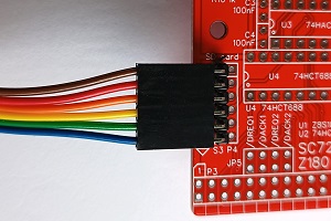


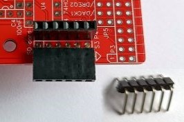
A choice of connectors is provided. The third option requires the adapter’s header pins to be straightened. In this configuration adapter prevents another module being fitted in the backplane slot immediately in front of it. Also, access to the micro SD card is restricted if there is a module in front of it. Using an adapter cable allows the SD card adapter to be mounted remotely.
- Resistors R1 to R12
These can be fitted either way around - Header sockets S1, S2 and optionally S3 (angled 6-pin sockets)
Ensure these are fitted flat against the circuit board - Decoupling capacitors C1 to C4 (100 nF)
These can be fitted either way around - Capacitors C5 and C6 (18 pF)
These can be fitted either way around - Sockets for U2, U3 and U4
Fit such that the notch in the socket matches the curve in the outline on the PCB silkscreen - Header pins P1 and P2, and optionally P4 (angled 6-pins)
Ensure the pins are parallel to socket S1 and S2, and optionally S3 - Angled header pins for jumper JP1
- Resistor networks RN1
This must be fitted the correct way around whereby the dot on the component matches the dot on the PCB silkscreen - Bus header P3
Make sure the pins are parallel to the PCB so that the board is vertical when it is fitted into a backplane socket - Crystal X1 (18.432 MHz)
This can be fitted either way around - Socket for U1
Ensure the orientation matches the outline on the PCB silkscreen - Light emitting diode LED1
Fit such that the short lead and/or small flat on the plastic is at the end marked with a line on the PCB silkscreen - Straight header pins for jumpers JP2, 3, 4 and 5
- Optionally, P4 (straight header socket)
- Insert the integrated circuits into their sockets
U1: Make sure the flat corner matches the small flat in the socket and also the position indicated on the PCB silkscreen
U2,3,4: Make sure the notch in the component is at the end indicated by the notch in the socket and the curve on the PCB silkscreen - Fit the nylon spacer in the mounting hole
Do not fit any jumper shunts at this time unless you are sure they are needed for your system configuration.
Compatibility
This module conforms to the RCBus specification v1.0 for full 80-pin modules.
The recommended memory module for use with this CPU is SC721.
The RCBus specification includes RCBus-2014 (both RC2014 standard 40-pin bus and RC2014 enhanced 60-pin bus) and also the full 80-pin RCBus. The 80-pin RCBus provides support for advanced Z80 features, such as the interrupt daisy-chain, as well as support for other processor families.
The table below indicates electrical compatibility with each backplane type (40, 60 and 80 pin)

| Backplane | ? | Compatibility notes |
| RCBus 80-pin |  | Fully supported |
| RCBus 60-pin (RC2014 enhanced) |  | A16 to A19 not supported |
| RCBus 40-pin (RC2014 standard) | | A16 to A19 not supported |
Notes
- This product is designed for hobby use and is not suitable for industrial, commercial, or safety-critical applications.
- The product contains small parts and is not suitable for young children.
- RomWBW is copyright Wayne Warthen and has been provided free of charge with his permission.
