SC115 is a prototyping breakout module designed for the RC2014 bus.
A later design is now available: SC724
Documentation
- SC115 – Assembly Guide (see user guide PDF)
- SC115 – User Guide (see user guide PDF)
- SC115 – Kit Contents Sheet (PDF)
- SC115 – Schematic r1.0.0 (PDF)
- SC115 – User Guide e1.0.1 (PDF)
Suppliers
| Kits | Website | From | Currency |
| Small Computers Direct | SCDirect | UK | GBP |
| Stephen C Cousins | Tindie | UK | USD |
| Small Computer Central | Lectronz | UK | Euro/USD |
| PCBs | Website | From | Currency |
| Small Computers Direct | SCDirect | UK | GBP |
| Stephen C Cousins | Tindie | UK | USD |
| Small Computer Central | Lectronz | UK | Euro/USD |
| Assembled and Tested | Website | From | Currency |
| Not available | |||
| Components | |||
| See parts list |
Tindie does not collect VAT for EU countries
Lectronz does collect EU VAT for orders up to 150 EUR
Description
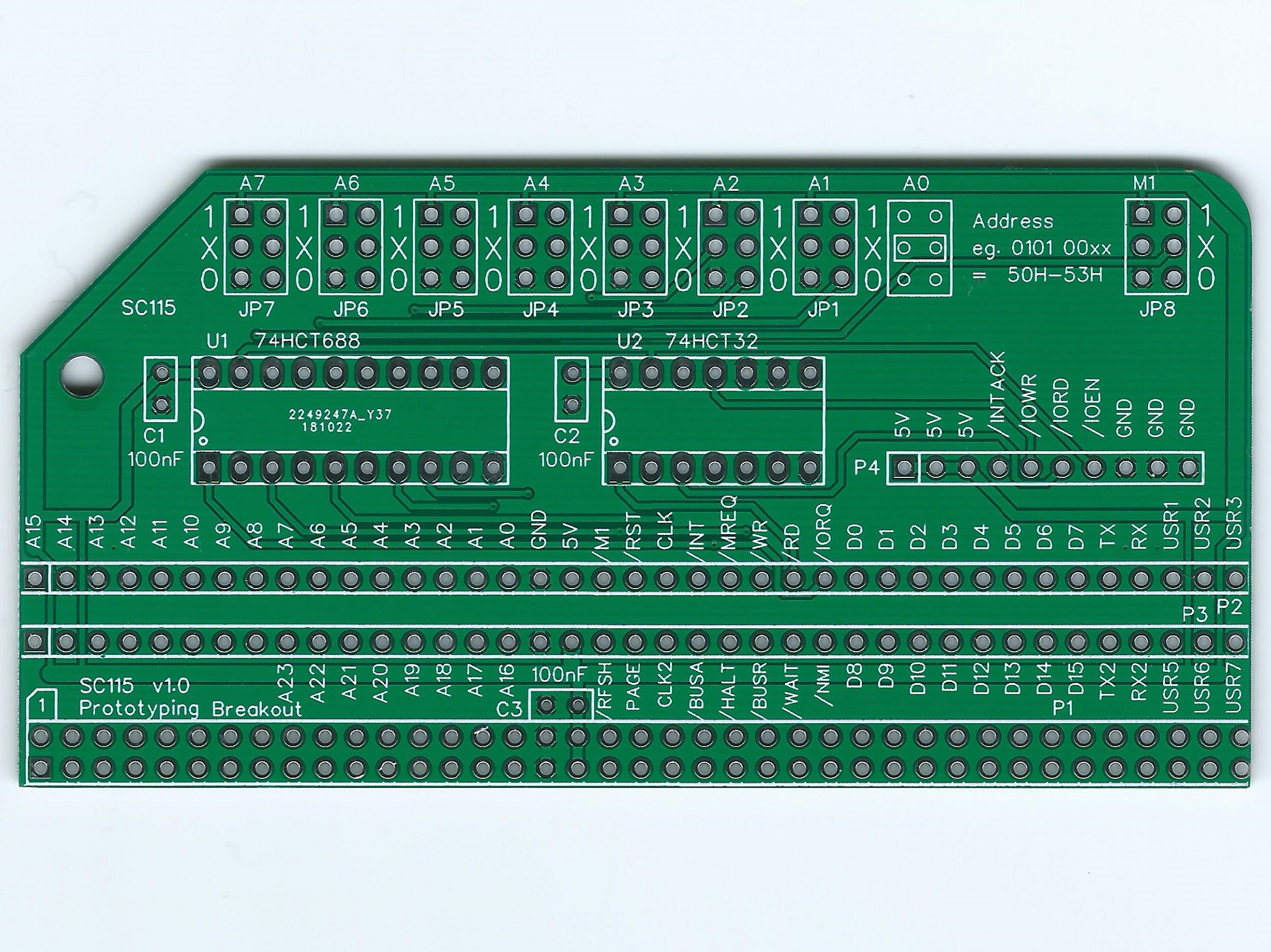
Signal breakout module PCB to aid prototyping of RC2014 modules on solderless breadboards.

This PCB is designed as an aid to prototyping RC2014 modules on solderless breadboards. It allows RC2014 bus signals to be easily connected to a breadboard with Dupont cables.

The board includes flexible I/O address decoding, so you don’t need to include such circuitry on every prototype. The decoding has jumpers to configure the start address and range. This includes allowing partial decoding with shadow addresses.
The address decoding circuit provides an I/O enable signal (/IOEN) and also separate read and write versions (/IORD and /IOWR). This range of enable signals allows easy interfacing to most I/O devices.
Features
- Easy access to RC2014 bus signals
- Flexible address decoding generates /IOWR, /IORD and /IOEN
- Connection to solderless breadboards with Dupont cables
Documentation, including assembly details: SC115 v1.0 User Guide (PDF)

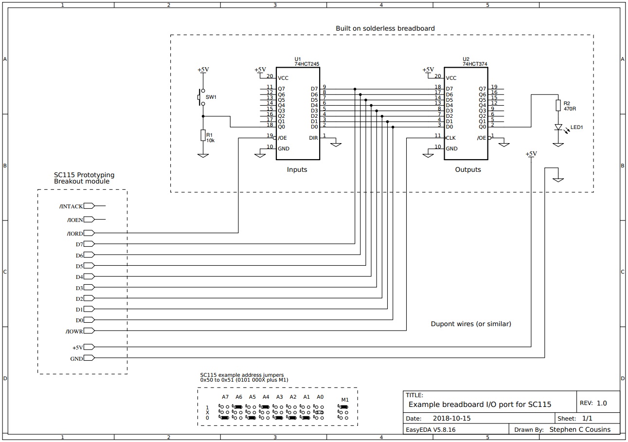
Download Schematic: SC115 v1.0 Schematic (PDF)
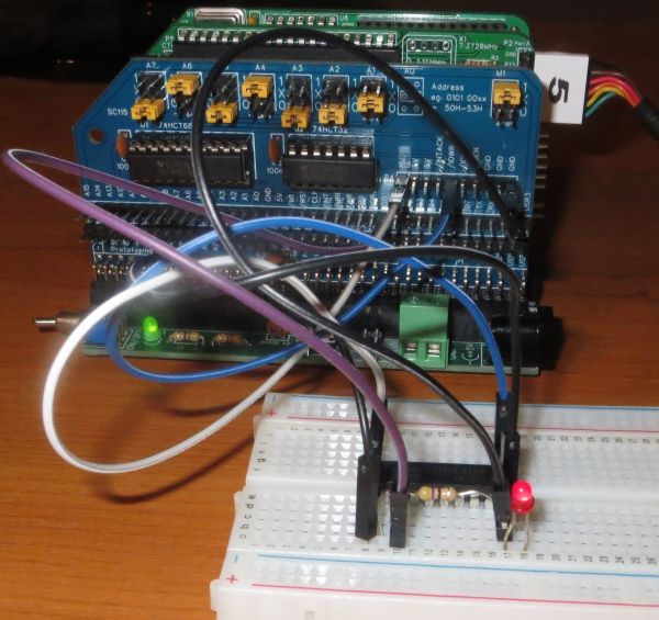
Here’s an example application. The module is breaking out signals to a couple of breadboards. One breadboard contains a simple digital input port and the other contains a simple digital output port.
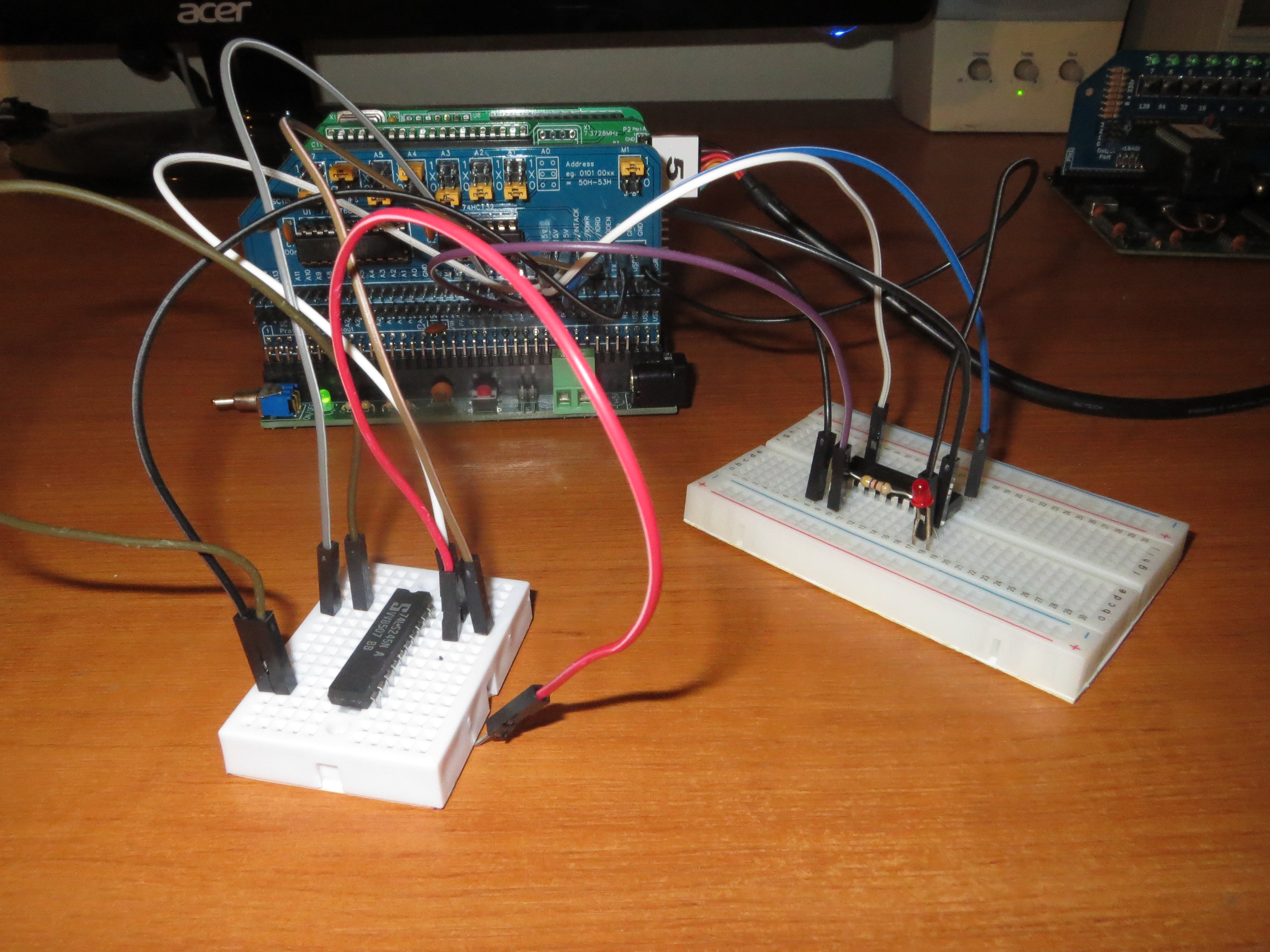
The above example application is wired as shown below.
Parts List
| Reference | Qty | Component |
| PCB | 1 | SC115, v1.0, PCB |
| C1 to C3 | 3 | Capacitor, ceramic, 100 nF |
| JP1 to JP8 | 8 | Header, male, 2 x 3 pin, straight |
| JP1 to JP8 shunts | 8 | Jumper shunt |
| P1 | 1 | Header, male, 2 x 39 pin, angled |
| P2 and P3 | 2 | Header, male, 1 x 39 pin, straight |
| P4 | 1 | Header, male, 1 x 10 pin, straight |
| U1 | 1 | 74HCT688 |
| U1 socket | 1 | 20-pin DIP socket |
| U2 | 1 | 74HCT32 |
| U2 socket | 1 | 14-pin DIP socket |
Printed Circuit Board
| Supplier | Website | Ships from |
| Stephen C Cousins | Tindie | UK |
| pcb4diy | eBay | Germany |
| pcb4diy | pcb4diy.de | Germany |
Notes
- This design is made in accordance with the “designed for RC2014” labelling scheme.
- RC2014 is a trademark of RFC2795 Ltd.
- This product is designed for hobby use and is not suitable for industrial, commercial or safety-critical applications.
- The product contains small parts and is not suitable for young children.
