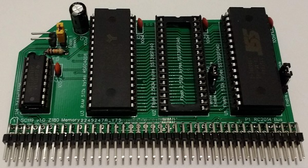
SC111 is a Z180 CPU module designed for the RC2014 bus.
A later design is now available: SC722
The SC111, Z180 CPU module, houses a Z8S180xx CPU. This CPU is basically a Z80 processor with lots of extra peripheral functions built in.

Documentation
- SC111 – Assembly Guide
- SC111 – Circuit Explained
- SC111 – Firmware
- SC111 – Software, CP/M 2.2 – see below
- SC111 – Software, SCM Apps
- SC111 – Support
- SC111 – System Options
Downloads
- SC111 – CP/M PutSysPlus for Z180 (HEX)
- SC111 – Firmware, RomWBW (Z180 native mode)
- SC111 – Firmware, SCM S4 (Z80 replacement mode)
- SC111 – Firmware, SCM S5 (Z180 native mode)
- SC111 – Schematic v1.0 (PDF)
Suppliers
| Kit Suppliers | Website | Ships from |
| Discontinued | ||
| PCB Suppliers | Website | Ships from |
| Small Computers Direct | SCDirect | UK |
| Stephen C Cousins | Tindie | UK |
| pcb4diy | pcb4diy.de | Germany |
| pcb4diy | eBay | Germany |
| Assembled and Tested | Website | Ships from |
| Not available | ||
| Component Suppliers | ||
| See parts list |
Description
The module provides two 5 volt FTDI style serial ports with software controlled baud rates. The processor’s clocked serial I/O port is available on a header. Also included is a voltage supervisor to give a clean, reliable reset.
The module will typically include an oscillator to provide the CPU with an 18.432 MHz clock. Overclocking, using the Z180’s software controlled clock multiplier, may be possible at 36 MHz.
The recommended firmware is detailed here.
Using the recommended firmware, there are two ways to use SC111, Z180 CPU Module:
- As a native Z180 module. The on-board serial ports, timer and memory management unit are used, but some software and hardware compatibility is sacrificed.
- As a replacement for a Z80 module. This gives good software and hardware compatibility, but does not make use of the Z180’s on-board peripherals, such as the serial ports.
Native Z180 Mode
This configuration requires a memory module designed for the Z180 CPU. This is a simple ‘linear’ memory map with 512k bytes of ROM (usually Flash) at the bottom of the physical memory space, and 512k bytes of RAM at the top. The following modules should be suitable, but only SC119 has been tested.
Note, the official RC2014 “512k ROM 512k RAM RomWBW module” is not suitable. This module includes its own memory management, so is not compatible with the simple ‘linear’ memory assumed for this configuration.
In order to support the extra address lines needed for 1M byte of memory, a suitable backplane is required. Currently, none of the official RC2014 backplanes carry the extra signals. However, the following backplanes do carry them.
- SC112, 6-slot modular backplane
- SC113, 6-slot modular backplane
- SC116, 3-slot backplane
- Others are also available. Look for backplanes with full 80-pin connectors.

Z80 Replacement Mode
In many cases SC111 is a drop in replacement for a simple Z80 module. However, it may require a 7.3728 MHz oscillator to maintain compatibility with existing software and hardware.
Existing CP/M configurations can be used, providing the memory board(s) support paging out ROM, by a write to I/O address 0x38, and allow a full 64k bytes of RAM to be enabled.
The official RC2014 “512k ROM 512k RAM RomWBW module” can be used with the Z180 module. Not tested!
The Small Computer Monitor and existing CP/M builds can be used with most common RC2014 compatible serial modules. However, this configuration does not support the Z180’s on-board serial ports.
User Guide
The SC111, Z180 CPU module can be used in two basic ways.
- Z180 native mode. This requires a matching Z180 Memory module, such as SC119, which provides 1 Megabyte.
- Z80 replacement mode. This allows use of 64k style memory modules, such as the RC2014 64k RAM module and the RC2014 pageable ROM module.

Both modes support the Small Computer Monitor and ROM BASIC, and both can run a suitable versions of CP/M. Z180 native mode also supports RomWBW, which provides a wealth of hardware support.
Firmware Options
Z180 native mode firmware:
- Small Computer Monitor, configuration S5
- RomWBW
Z80 replacement mode firmware:
- Small Computer Monitor, configuration S4
Software Options
Z180 native mode software:
Z80 replacement mode software:
- After starting from SCM S4, most software for RC2014-Z80 should run.
DCD Input
A jumper shunt should be fitted to JP9, as illustrated below.
Some versions of the Z180 require the DCD input to be low for the serial port to work correctly. Other versions allow the serial port to operate with the DCD input either high or low. In the latter case, this pin can be read in software making in a general purpose input. To allow for all versions of the Z180 a jumper shunt should be fitted to JP9, pulling the DCD input low.

Power
A system using this module can be powered from the backplane, or from either of the built-in asynchronous serial ports.
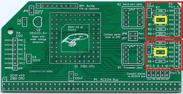
Each serial port, highlighted below in red, can supply power to the system. To connect power from a serial port, fit a jumper shunt in the appropriate location, indicated below in yellow. The top jumper is for port A and the bottom jumper is for port B.
WARNING: You should normally only connect one power source to the system, at any time.
As power can flow either way, these jumpers also enable serial devices to be powered from this module. If such devices are used, fit a jumper shunt in the appropriate position, indicated above in yellow.
Serial Port Clock Source
Current firmware and software for this module assume the built-in serial ports use the main processor oscillator (X1) as their clock source. However, the module allows a separate oscillator (X2), shown below in red, to be used instead.
If you wish to experiment with this option, fit a suitable oscillator in position X2. Also, fit jumper shunts to both JP7 and JP8, indicated below in yellow. In addition, you will need appropriate firmware to match. This requires study of the CPU’s datasheet!

Do NOT fit jumper shunts to JP7 and JP8 when using ‘standard’ distribution firmware and software designed for this module.
In normal operation, just leave this header unconnected.
Clocked Serial I/O
The CPU’s built-in clocked serial I/O port is available at the connector P4. This has to potential to provide a fast SPI, or similar, port, but requires appropriate software.

In normal operation, just leave this header unconnected.
CP/M
A version of CP/M 2.2 is available for SC111, Z180 CPU module.
New versions, together with more detailed instructions, are available here.
This version is specifically for SC111 (Z180 CPU module) plus SC119 (Z180 memory module), with the Small Computer Monitor v1.0 configuration S5 in ROM.
It supports the two serial ports on module SC111, and the official RC2014 Compact Flash module (or compatible). CP/M uses the serial ports with the settings supplied by the Small Computer Monitor.
The CP/M software is supplied (below) in the form of a “PutSys” program. This program is loaded and run from the Small Computer Monitor and installs CP/M to a formatted Compact Flash card. Once installed to Compact Flash, CP/M can be started with the command “CPM”, from the Small Computer Monitor.
Downloads
This file is required to set up CP/M on the Z180 system:
Instructions
Instructions to install CP/M 2.2 on to a Compact Flash card can be found here.
Parts List
| Reference | Qty | Component |
| PCB | 1 | SC111, v1.0, PCB |
| C1 to C5 | 5 | Capacitor, ceramic, 100 nF |
| C6 | 1 | Capacitor, ceramic, 1 nF |
| JP 1, 2, 9 | 3 | Header, male, 1 x 2 pin, straight |
| JP3 plus 4, 5, 6, 10 | 1 | Header, male, 2 x 5 pin, straight |
| JP7 plus JP8 | 1 | Header, male, 2 x 2 pin, straight |
| Jumper shunts | 9 | Jumper shunt |
| P1 | 1 | Header, male, 2 x 39 pin, angled |
| P2 and P3 | 2 | Header, male, 1 x 6 pin, angled |
| P4 | 1 | Header, male, 1 x 7 pin, angled |
| R1 to R6 | 6 | Resistor, 2k2, 0.25W |
| R7 to R9 | 3 | Resistor, 100k, 0.25W |
| RP1 | 1 | Resistor pack, 8 x 10k, SIL, 9-pin |
| U1 | 1 | Z8S18033VSG (Z180 CPU) or Z8S18033VSC or Z8S18020VSG or Z8S18020VSC |
| U1 socket | 1 | 68-pin PLCC socket |
| U2 | 1 | DS1233-5+ EconoReset |
| X1 | 1 | Oscillator 18.432 MHz |
| X1 socket | 1 | 8-pin PDIP socket (optional) |
| X2 | – | Not fitted |
PCB

| Supplier | Website | Ships from |
| Stephen C Cousins | Tindie | UK |
| pcb4diy | eBay | Germany |
| pcb4diy | pcb4diy.de | Germany |
Older Versions
Notes
- This design is made in accordance with the “designed for RC2014” labelling scheme.
- RC2014 is a trademark of RFC2795 Ltd.
- This product is designed for hobby use and is not suitable for industrial, commercial or safety-critical applications.
- The product contains small parts and is not suitable for young children.
