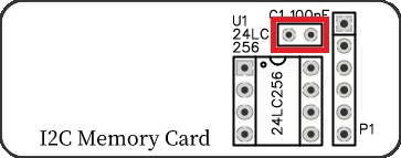
SC138 is a 32k byte I2C memory card.

- SC138 – Forum (rc2014)
- SC138 – Forum (retro-comp)
- SC138 – Kit contents sheet (PDF)
- SC138 – Schematic v1.0 (PDF)
- SC138 – Example I2C code
Suppliers
| Kits | Website | From | Currency |
| Small Computers Direct | SCDirect | UK | GBP |
| Stephen C Cousins | Tindie | UK | USD |
| PCBs | Website | From | Currency |
| Small Computers Direct | SCDirect | UK | GBP |
| Stephen C Cousins | Tindie | UK | USD |
| Assembled and Tested | Website | From | Currency |
| Not available | |||
| Components | |||
| See parts list |
Description
SC138 is a 32k byte I2C bus memory card.
The memory card contains a 24LC256 (32k by 8 bit) EEPROM. This device can store 32k bytes of data and then retain that data without power.
The device uses a simple 5 volt I2C bus to read and write the data.
The goal is to add SAVE and LOAD functions to the Small Computer Monitor (SCM) and ROM BASIC.
The main features of this design are:
- I2C bus compatible (5 volts)
- 32k by 8 bit non-volatile memory
- Low cost
- Compatible with SC126 and SC137
User Guide
The memory card contains a 24LC256 (32k by 8 bit) EEPROM. This device can store 32k bytes of data and then retain that data without power.
The device uses a simple 5 volt I2C bus to read and write the data.
Address
The 24LC256 has a fixed address on the I2C bus of binary:
1 0 1 0 1 1 1 x
where x is 1 for read or 0 for write.
In hexadecimal, the I2C bus device address is 0x57. It can also be thought of as an 8-bit address byte with 0xAE for write and 0xAF for read.
Software
Example source code can be found here.
The goal of this project is to add SAVE and LOAD functions to the Small Computer Monitor (SCM) and to ROM BASIC.
Parts List
| Reference | Qty | Component |
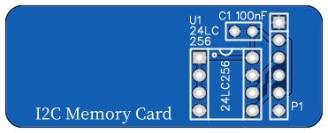
| PCB | 1 | SC138, v1.0, PCB |
| C1 | 1 | Capacitor, ceramic, 100 nF |
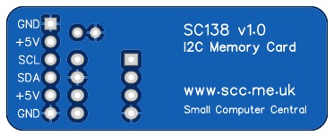
| P1 | 1 | Header, female, 1 x 6 pin, angled |
| U1 | 1 | 24LC256 |
Printed Circuit Board
| Links |
| SC138, v1.0, PCB only (Tindie) |
| SC138, v1.0, Complete kit (Tindie) |
| SC138, v1.0, PCB design files (OSHWLab) |
| SC138, v1.0, Gerber files (ZIP) |
Assembly Guide
Experienced builders can just go ahead and populate the board. There shouldn’t be any surprises to catch you out.
Introduction
This guide assumes you are familiar with assembling circuit boards, soldering, and cleaning. If not, it is recommended you read some of the guides on the internet before continuing.
First check you have all the required components.
Before assembling it is worth visually inspecting the circuit board for anything that looks out of place, such as mechanical damage or apparent manufacturing defects.
If you have a multimeter that measures resistance or has a continuity test function, check there is not a short on the power supply tracks. Connect the probes to each terminal of capacitor C1. This should be an open circuit, not a short.
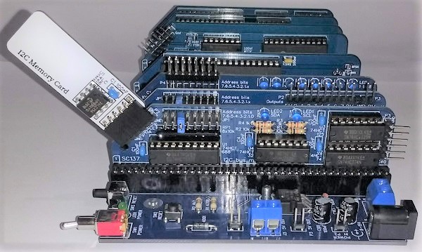
The picture below shows what a completed SC138, I2C memory card should look like.
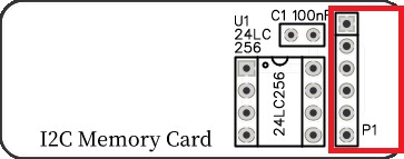
Header
Fit and solder the 6-pin angled female header P1.

Integrated Circuit 24LC256
Fit and solder the integrated circuit (24LC256) U1.
Be sure to fit the IC with the notch matching the legend on the circuit board.

Capacitor 100 nF (0.1 µF)
Fit and solder 100nF capacitor C1.
This capacitor can be fitted either way around, as it is not polarity dependent.
The exact value of this component is not critical. The use of very cheap capacitors within the range of about 30 to 200 nF is acceptable.
Inspection
Remove any solder ‘splats’ with a brush, such as an old toothbrush.
Visually inspect the soldering for dry joints and shorts.
Clean the flux off with suitable cleaning materials.
Visually inspect again.
Notes
- This product is designed for hobby use and is not suitable for industrial, commercial or safety-critical applications.
- The product contains small parts and is not suitable for young children.
