SC522 is a modular backplane designed for Z50Bus.
Documentation
- SC500 – Series Information
- SC522 – Description
- SC522 – Assembly Guide
- SC522 – Parts List
- SC522 – Printed Circuit Board
- SC522 – Support
- SC522 – User Guide
Downloads
Kits
Older Versions
- none
Description
SC522 is a modular backplane designed for Z50Bus.
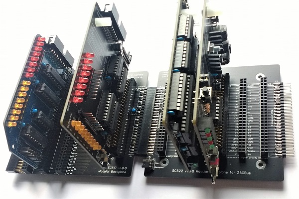
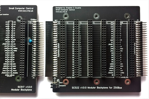
This modular backplane section can be connected to other Z50Bus compatible modular backplanes.
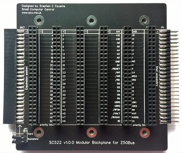
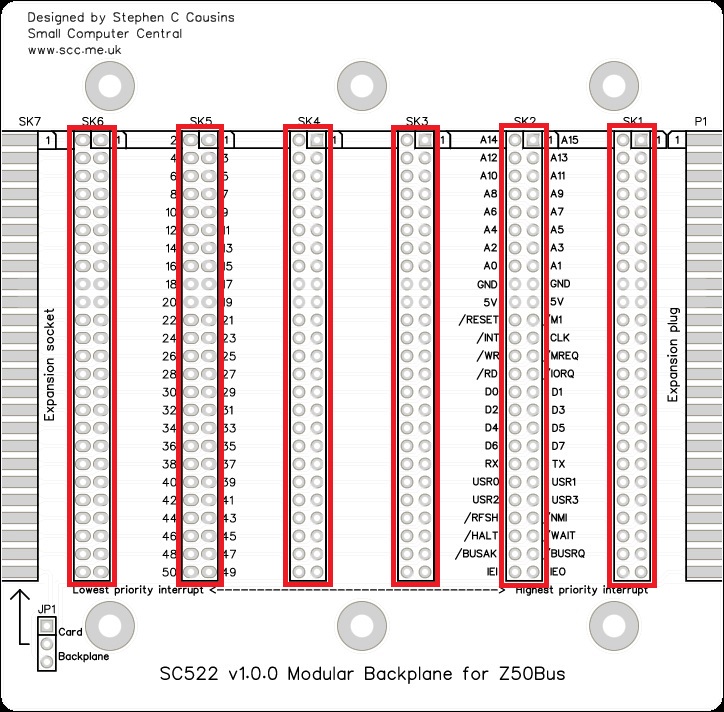
SC522 has 6 vertical Z50Bus sockets, with narrow (0.6″) spacing. It also has horizontal Z50Bus connectors on the ends.
The main features of this design are:
- Modular (extendable) design
- Six Z50Bus sockets
- Simple passive design
- Compact 0.6″ (15.24mm) slot spacing
User Guide
SC522 is a modular backplane designed for Z50Bus.
This modular backplane section can be connected to other Z50Bus compatible modular backplanes, or to the LiNC80 SBC1.
This modular backplane can be used with the following modular backplane sections and Z50Bus compatible products:
- Z50Bus compatible products
- SC513 Modular backplane for Z50Bus
- SC522 Modular backplane for Z50Bus
- SC128 Modular backplane for Z50Bus
- LiNC Z50Bus 5-slot backplane
- LiNC80 SBC1
Cards can be placed in any socket, the position and order does not usually matter. However, there are a few exceptions.
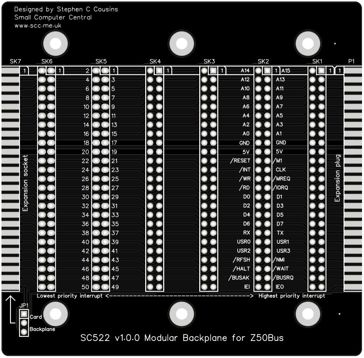
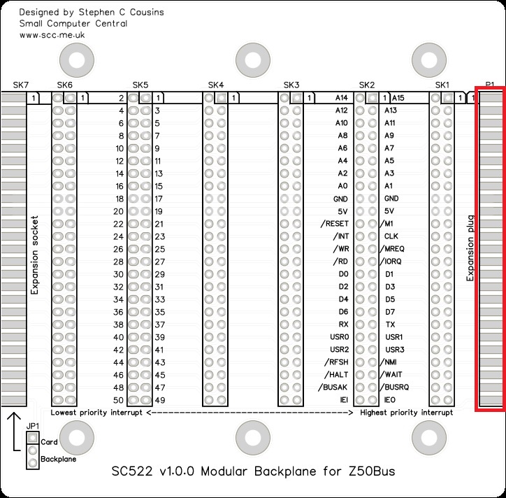
- Cards using Z80 mode 2 interrupts need to be grouped together with the highest priority interrupting device to the right (as illustrated above). These cards are linked by a daisy-chain which is incorporated into the backplane. As a result you must not leave an empty slot between any cards generating interrupts.
- Simple Compact Flash storage cards that essentially connect directly to the processor bus sometimes need to be in a socket near to the processor or they can be unreliable.
Parts List
| Reference | Qty | Component |
| PCB | 1 | SC522, v1.0, PCB |
| JP1 | 1 | Header, male, 1 x 3 pin, angled |
| Jumper shunts | 1 | Jumper shunt |
| P1 | 1 | Header, male, 2 x 25 pin, straight |
| SK1 to SK7 | 7 | Header, female, 2 x 25 pin, straight |
| Feet | 6 | Self-adhesive feet, or Other PCB support |
Printed Circuit Board
| Supplier | Website | Ships from |
| Stephen C Cousins | Tindie | UK |
| pcb4diy | pcb4diy.de | Germany |
| pcb4diy | eBay | Germany |
Assembly Guide
Experienced builders can just go ahead and populate the board. There shouldn’t be any surprises to catch you out.
This guide assumes you are familiar with assembling circuit boards, soldering, and cleaning. If not, it is recommended you read some of the guides on the internet before continuing.
First check you have all the required components, as listed in the parts list.
Before assembling it is worth visually inspecting the circuit board for anything that looks out of place, such as mechanical damage or apparent manufacturing defects.
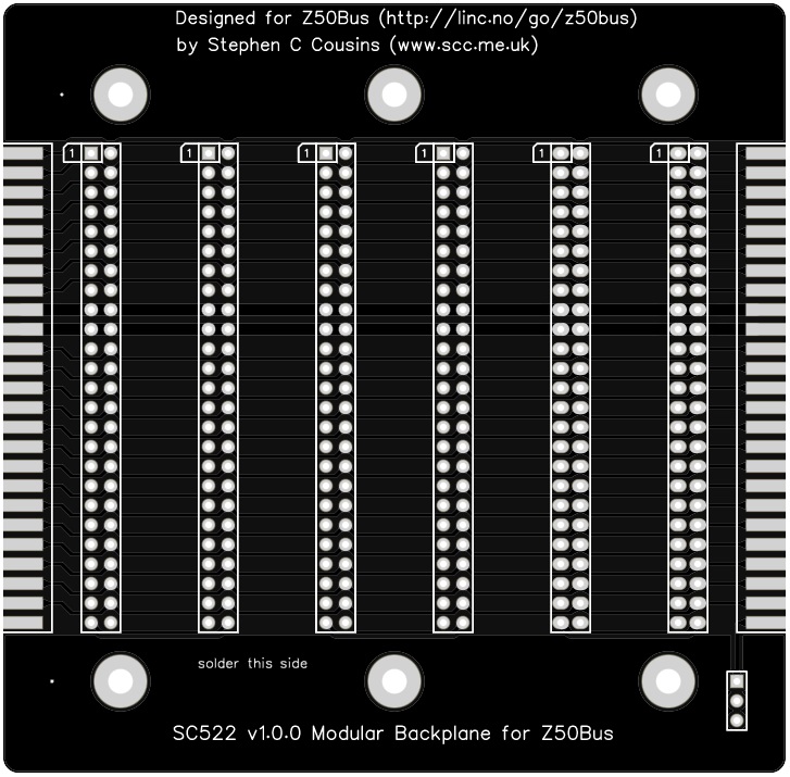
The picture below shows what a completed SC522 Modular Backplane should look like.
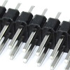
Male bus header
Fit and solder the Z50Bus male bus header pins, P1 (shown below in red).
This fits over the edge of the PCB as illustrated above.
A good strategy for fixing this so the pins are parallel to the circuit board is to solder one pin near each end, on one side of the board. Check the pins are parallel and adjust if necessary. Now solder a similar pair of pins on the other side, and again adjust as necessary. Now solder a few on each side, then swap sides until all the pins are soldered.
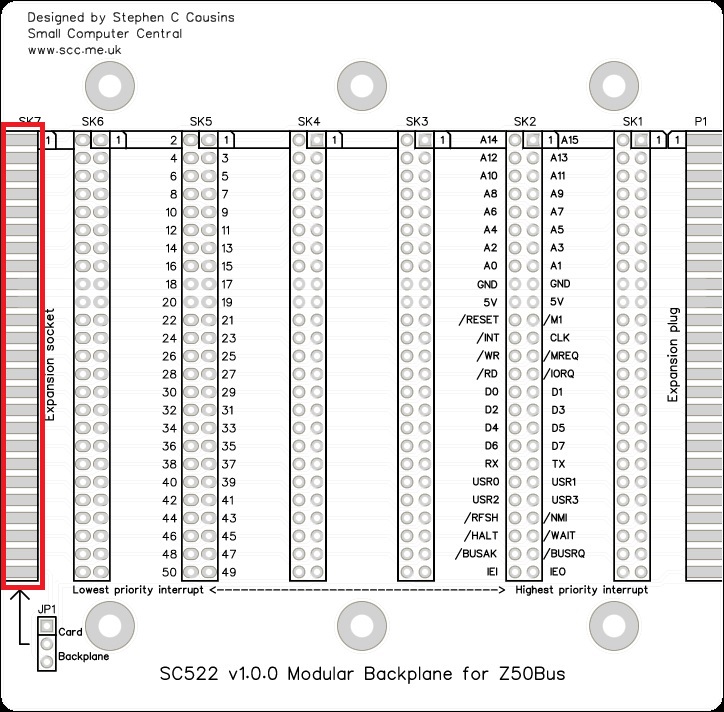
Expansion socket
Fit and solder the female header.
This fits over the edge of the PCB as illustrated above.

Card sockets
Fit and solder the Z50Bus sockets.
Inspection
Remove any solder ‘splats’ with a brush, such as an old toothbrush.
Visually inspect the soldering for dry joints and shorts.
Clean the flux off with suitable cleaning materials.
Visually inspect again.
If all is well, go ahead and give it a try.
Notes
- This design is made with the permission of LiNC (designers of the Z50Bus).
- This product is designed for hobby use and is not suitable for industrial, commercial ,or safety-critical applications.
- The product contains small parts and is not suitable for young children.
