SC516 is a Z80 processor card designed for Z50Bus.

Documentation
- SC500 – Series Information
- SC516 – Description
- SC516 – Assembly Guide
- SC516 – Circuit Explained
- SC516 – Firmware, SCM F1
- SC516 – Parts List
- SC516 – Printed Circuit Board
- SC516 – Software, CP/M 2.2
- SC516 – Software, SCM Apps
- SC516 – Support
- SC516 – User Guide
Downloads
Kits
Description
SC516 is a Z80 processor card designed for Z50Bus.
Here are the specs:
- Z80 running at 7.3728 MHz
- 128k bytes RAM (second 64k not easy to use, so best consider it to be 64k usable)
- 32k bytes ROM, which can be paged out with a single write to port 0x38
- LED for power and status indication
- Simple 9600 baud serial port
- Runs the Small Computer Monitor, with ROM BASIC and the CP/M loader included
If you want to run CP/M you will need to add is a Z50Bus Compact Flash interface, such as SC504, and a Compact Flash card with a suitable CP/M distribution installed. You will probably also want to add a more sophisticated serial card, such as SC511. All this is supported by the ROM with no configuration required.
Parts List
| Reference | Qty | Component |
| PCB | 1 | SC516, v1.0, PCB |
| C1 to C7 | 7 | Capacitor, ceramic, 100 nF |
| JP1 | 1 | Header, male, 1 x 2-pin, straight |
| Jumper shunts | 3 | Jumper shunt Two used to pad box header |
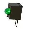
| LED1 | 1 | LED, green, 3mm, angled |
| P1 | 1 | Box header, 2 x 25 pin, angled, or Header, male, 2 x 25 pin, angled |
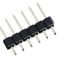
| P2 | 1 | Header, male, 1 x 6-pin, angled, or Header, male, 1 x 6-pin, straight |
| R1 | 1 | Resistor 10k 0.25W |
| R2 | 1 | Resistor, 1k, 0.25W |
| RN1 | 1 | Resistor pack, 8 x 10k, SIL, 9-pin |
| Spacer | 1 | Spacer, 10mm, M3, nylon |
| Screw (for spacer) | 1 | Machine screw, 6mm, M3 |
| U1 | 1 | Z80 CPU Z84C0008PEG, or Z80 CPU Z84C0010PEG |
| U1 socket | 1 | 40-pin DIP socket |
| U2 | 1 | RAM 128k bytes AS6C1008 |
| U2 socket | 1 | 32-pin DIP socket |
| U3 | 1 | EPROM OTP 32k bytes 27C256 |
| U3 socket | 1 | 28-pin DIP socket |
| U4 | 1 | 74HCT259 |
| U4 socket | 1 | 16-pin DIP socket |
| U5 | 1 | 74HCT4075 |
| U5 socket | 1 | 14-pin DIP socket |
| X1 | 1 | Oscillator 7.3728 MHz |
| X1 socket | 1 | 8-pin PDIP socket (optional) |
Printed Circuit Board
| Supplier | Website | Ships from |
| Stephen C Cousins | Tindie | UK |
| pcb4diy | pcb4diy.de | Germany |
| pcb4diy | eBay | Germany |

User Guide
SC516 is a Z80 processor card designed for Z50Bus.
The card can be used in two basic ways:
- As a Single Board Computer (SBC).
- As the processor card in a Z50Bus system.
Single Board Computer
This card can be used in a modest say as a Single Board Computer. The card is connected to a computer or terminal with an FTDI style serial adapter. The adapter also provides the 5V 100mA power for the card. A reset signal will also need to be provided.
This serial port is very basic, providing only a software-generated 9600 baud, 8 data bit, 1 stop bit, no parity serial interface. It is designed to provide a very low-cost ‘starter’ port to get the system up and running as easily and cheaply as possible. It is suitable for simple applications, but a more capable serial module should be added for sophisticated applications such as running CP/M.
The pin-out, below, describes signals with respect to the card, so an output is a signal from the card to a computer or terminal.
| Pin | Function |
| 6 | Clear To Send (CTS) input (not connected) |
| 5 | Transmit Data (TxD) output |
| 4 | Receive Data (RxD) input |
| 5 | Vcc (5V) |
| 2 | Request To Send (RTS) output |
| 1 | Ground (GND) |
Z50Bus System
A more capable system can be created using this card as the processor and memory for a Z50Bus computer.
The most likely first addition would be an SC511, Serial card. This provides two asynchronous serial ports, software controlled baud rates, and a timer.
Status LED
When using the Small Computer Monitor ROM, pressing the reset button should cause the status LED to flash off and on again, either once or twice.
- One flash off and on indicates a serial module has been detected on the bus and is being used to connect to a terminal. Serial cards usually work at 115200 baud, 8 data bits, 1 stop bit, no parity and hardware flow control (RTS/CTS).
- Two flashes off and on indicate a serial card has not been detected and the onboard serial port (P1) is being used to connect to a terminal. This port works at 9600 baud, 8 data bits, 1 stop bit, no parity and hardware flow control (RTS/CTS).
- If the LED continues to flash the self-test has failed, most likely indicating the RAM is not working.
Quick Start Guide
Below is a very brief guide to getting started with the SC516, Z80 Processor Card.
The ROM should contain the Small Computer Monitor.
It is assumed that this card is plugged into a Z50Bus compatible backplane, and that power and reset are provided to the backplane. This can either be from a dedicated power supply card (such as SC502) or from a backplane with its own power supply (such as SC513).
With power provided from the backplane, there should not be a jumper shunt connected to JP1. This jumper allows the system to be powered from the serial port, but you should only have one power source connected at a time.
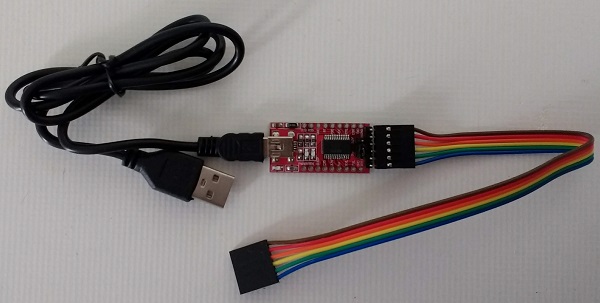
Connect a suitable FTDI style TTL level serial to USB adapter from P2 to a USB socket on a PC (or similar). These adapters come in many different shapes and sizes. The picture below shows one possible configuration.
Press the system’s reset button and check the LED lights. It should flash off and on again, twice, and then remain on.
Start a suitable terminal emulation program, such as Tera Term, on the PC (or equivalent). Configure the PC’s serial port for 9600 baud, 8 data bits, 1 stop bit, no parity, and hardware flow control (RTS/CTS). There is no need to set the terminal software to add delays. Almost any terminal emulation should work with the Small Computer Monitor.
Press the system’s reset button. You should see the terminal program display something like “Small Computer Monitor”.
You are now ready to play!
Software, CP/M
A version of CP/M 2.2 is available for SC516, Z80 Processor card.
New versions, together with more detailed instructions, are available here.
This version is designed for a Z50Bus system with the following hardware:
- Z80 Central Processing Unit (CPU), SC516 or SC518+SC519
- Z80 Serial Input/Output device (SIO), SC511 or SC521
- Compact Flash card (64MB or 128MB+), SC504
The CP/M software is supplied (below) in the form of a “PutSys” program. This program is loaded and run from the Small Computer Monitor and installs CP/M to a formatted Compact Flash card. Once installed to Compact Flash, CP/M can be started with the command “CPM”, from the Small Computer Monitor.
Downloads
The Compact Flash card needs to be formatted before CP/M is installed.
- SCM_App_CF_Format_1.0.0_2022_03_02.zip (includes source)
One of these files is required to set up CP/M on the Z50Bus system. The first is for a system with a 64MB Compact Flash card, the second is for a 128MB or larger card. CP/M 2.2 supports a maximum of 128MB with any additional space on the card not being used.
Instructions
Instructions to install CP/M 2.2 onto a Compact Flash card can be found here.
Assembly Guide
Important note: How to modify box headers
Experienced builders
There is only one suggested build option to watch out for. You can fit either a straight or a right angled header to P2 (serial port). Other than that there shouldn’t be any surprises to catch you out, so experienced builders can just go ahead and populate the board.
This guide assumes you are familiar with assembling circuit boards, soldering, and cleaning. If not, it is recommended you read some of the guides on the internet before continuing.
First check you have all the required components, as listed in the parts list.
Before assembling it is worth visually inspecting the circuit board for anything that looks out of place, such as mechanical damage or apparent manufacturing defects.
If you have a multimeter that measures resistance or has a continuity test function, check there is not a short on the power supply tracks. Connect the probes to each terminal of one of the capacitors, such as C1. This should be an open circuit, not a short circuit.
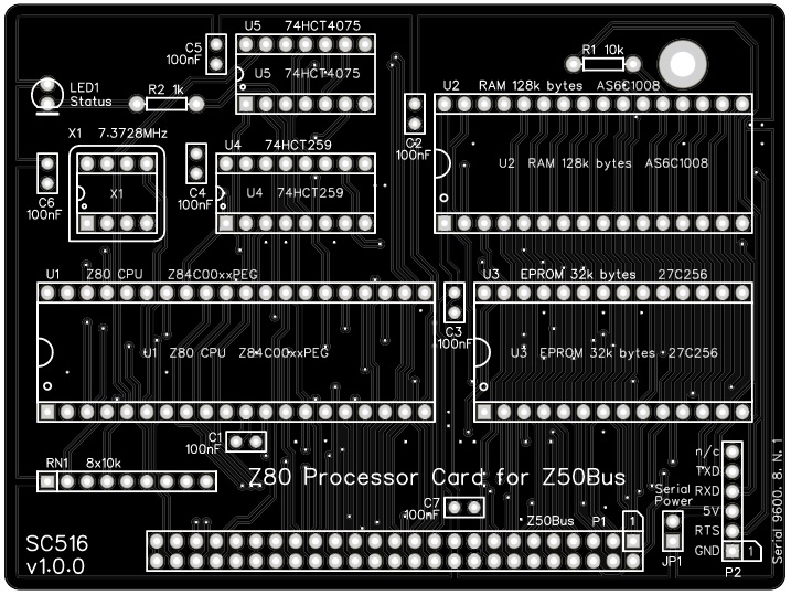
The picture below shows what a completed SC516, Z80 Processor Card should look like.
Resistors
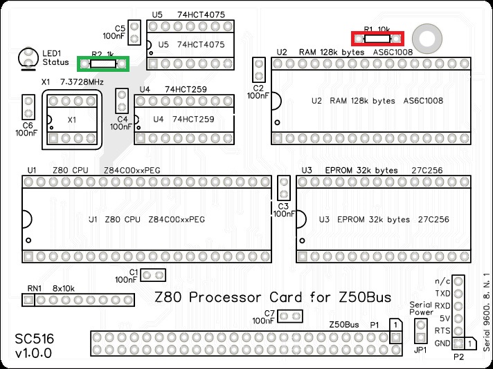
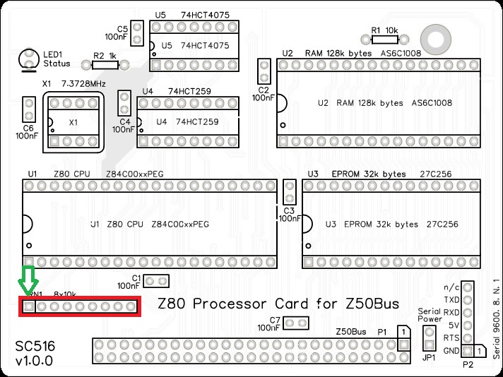
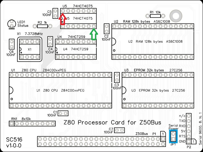
Fit and solder the 10k resistor R1 (shown below in red).

Fit and solder the 1k resistor R2 (shown below in green).

These can be fitted either way around, as they are not polarity dependent.
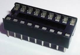
IC sockets
Fit and solder IC sockets for U1 to U5 (shown below in red).
You may wish to fit a socket for oscillator X1 (shown below in green). My preference is to solder this component, which you do later.
Be sure to fit them with the notch matching the legend on the circuit board, so you do not end up fitting the IC the wrong way around too.


Capacitors
Fit and solder capacitors C1 to C7.
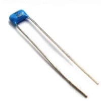
These can be fitted either way around, as they are not polarity dependent.

Resistor network
Fit and solder the 8x10k resistor network, RN1.
The 10k network will be marked 102.
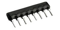
Take care to fit the resistor network the correct way around. Pin 1 is usually marked with a dot. This end is indicated on the PCB and on the illustration below.

Light Emitting Diode (LED)
Fit and solder green LED, LED1.
If using an angled LED the polarity is predefined and matches the PCB.
If using standard LEDs care must be taken to ensure they are fitted the correct way around.
It is important to fit the LED the correct way around. LEDs usually have a small flat side to indicate the cathode (the negative end). This should be positioned to match the flat side shown on the circuit board (illustrated to the right). Also, the cathode pin on the LED is usually shorter than the other pin (the Anode).


Power Header
Fit and solder header pins JP1.
This header may need to be cut down from a longer strip.

Serial Header
Fit and solder connector P2.
You can either fit straight pins or angled pins.
Angled pins generally give better access when mounted on a backplane, but fit straight pins if the card is to be used with card guides as suggested in the Z50Bus specification.
This header may need to be cut down from a longer strip.
Take care to ensure the pins are perpendicular (straight pin) or parallel (angled pins) to the circuit board.

Bus connector
Fit and solder the bus connector, P1. This can either be a right-angled box header or right-angled header pins. The box header is recommended.
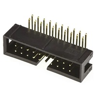
Take care to ensure the connector is fitted such that the card will stand vertically when fitted to a backplane. A good method is to just solder two pins, one at each end, and then check it looks correct. Then solder two more, one at each end but in the other row, and check again. At each stage, if necessary, adjust the position by heating the required solder joint and moving the connector slightly. Solder two pins in the middle of the connector and check again. Then solder all the others.

Inspection
Remove any solder ‘splats’ with a brush, such as an old toothbrush.
Visually inspect the soldering for dry joints and shorts.
Clean the flux off with suitable cleaning materials.
Visually inspect again.
Fit a jumper shunt to JP1, shown below in blue. This allows the circuit board to be powered from the serial port.
With a suitable FTDI style TTL level serial to USB adapter connected from P2 to a powered USB socket.
Check the supply voltage on this circuit board between U5 pin 7 and U5 pin 14. This should be 4.5 to 5.5 volts, preferably 4.75 to 5.25 volts. Unplug the serial adapter.
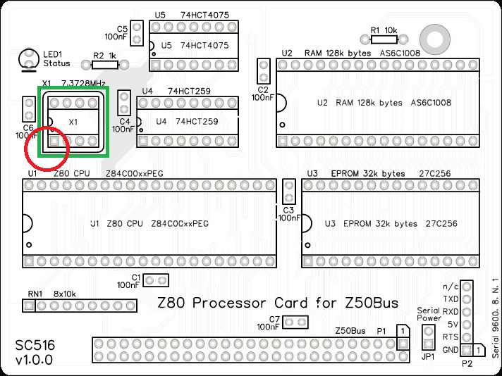
Oscillator
If you decided to solder the 7.3727 MHz oscillator, be sure to fit it the correct way around.
Pin 1 of the oscillator is normally indicated by a ‘sharp’ corner, while the other three corners are rounded.
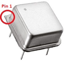
Pin 1 on the circuit board is also indicated by a ‘sharp’ corner, while the other three corners are rounded.

Integrated Circuits
Insert the ICs into their sockets, taking care to insert them the right way around, as illustrated below. Be careful not to bend any legs over. ICs are usually supplied with the legs slightly spread out making them difficult to insert. It is best to bend the two rows of legs so they are parallel before inserting them. Remember, these components can be damaged by static electricity so if possible earth yourself and the components while handling them.

Getting Started
The SC516 User Guide includes a brief guide to getting started.
Fault Finding
Check there are no chips with bent legs and thus not making contact with their socket, carefully inspect all soldering, check all the chips are inserted the right way around, check all the components are in the right place.
With a suitable FTDI style TTL level serial to USB adapter connected from P2 to a powered USB socket, check the supply voltage on this circuit board between, say, U5 pin 7 and U5 pin 14. This should be 4.5 to 5.5 volts, preferably 4.75 to 5.25 volts.
Check the LED is on. If it is not, then check the LED is the correct way around. Also check the RESET signal is high but goes low when the reset button is pressed. The LED should light when U4 is powered and working, and the RESET signal on U4 pin 15 is low.
If the LED is working, check it flashes off then on again, either once or twice after a reset. If it flashes then the board is running code successfully. This would indicate that all the main components are generally working. If the LED flashes off once after reset the system has detected a serial card plugged into one of the Z50Bus. If it flashes off twice it has not detected a serial card and is using the onboard serial port (P2). If it keeps flashing the self-test has failed, most likely indicating the RAM is not working.
Circuit Explained
The SC516, Z80 Processor card is part of a modular computer based on the Z50Bus. With the addition of power and a reset signal, it can also be used in a modest way as a Single Board Computer (SBC).
C1 to C7
These capacitors provide power supply decoupling (or bypass). The fast switching in digital circuits creates spikes on the power supply lines which are suppressed with decoupling capacitors placed at key points on the circuit board.
JP1
This jumper allows the card’s 5-volt power rail to be connected to the Vcc (5-volt) pin of the serial port (P2). Fitting a jumper shunt here connects the power between the two. Not fitting a shunt isolates the power between them.
There are two scenarios where you may want to fit the shunt:
- If the serial device needs power from the processor card
- If you are powering the Z80 system from the serial port.
You should not connect two power sources together, so do not fit the shunt if both the processor card and the serial device have independent power supplies.
LED1
This LED is a simple status indicator. It is normally on when the power is connected, but it can be controlled by software if required. At reset is will turn on, even if the processor is not running.
When using the recommended firmware it will then turn off and on again, indicating the processor is running. If a suitable serial port module is not found in any of the bus sockets, the LED will turn off and on again to indicate the built-in serial port is being used. A startup message is then sent to the terminal via the serial port indicated.
P1
This is the standard Z50Bus connector.
P2
The card includes a simple bit-bang 5 volt, FTDI style, serial port. The connection to this is the 6-pin header, P2. You can either fit straight or right-angled header pins. The angled connector is usually more convenient. If the card is to be supported by guides, as suggested in the Z50Bus specification, then straight pins must be fitted.
This port is very basic, providing only a software generated 9600 baud, 8 data bit, 1 stop bit, no parity serial interface. It is designed to provide a very low-cost ‘starter’ port to get the system up and running as easily and cheaply as possible. It is suitable for simple applications, but a more capable serial module should be added for sophisticated applications such as running CP/M.
The pin-out, below, describes signals with respect to the SC516 card, so an output is a signal from the card to a computer or terminal.
| Pin | Function |
| 6 | Clear To Send (CTS) input (not connected) |
| 5 | Transmit Data (TxD) output |
| 4 | Receive Data (RxD) input |
| 3 | Vcc (5V) |
| 2 | Request To Send (RTS) output |
| 1 | Ground (GND) |
R1
R1 limits the current from the serial receive input of P2.
R2
This resistor sets the LED current. You may change this value from about 330R to 1K depending on the type of LED you fit and your preference for brightness. A value of 1k will work fine with just about any LED, so if in doubt use this value.
RN1
This resistor network provides pull-ups for bus signals that may otherwise be left floating, or are used with open collector signals.
U1
This integrated circuit is the Z80 Central Processing Unit (CPU). A minimum of an 8 MHz rated part is required, but a faster part can also be used. The CPU is the brains of the board. It is able to execute instructions stored in the read-only memory (ROM) chip U3 or programs downloaded or written to the random access memory (RAM) chip U2.
For further details see the Zilog CPU datasheet.
U2
This is the motherboard’s Random Access Memory (RAM). Although this is a 128k byte RAM chip, the Z80 CPU can only ‘see’ 64k bytes at any given time. The second 64k bytes can be selected in software, but it is quite difficult to use. In practice, it is likely that only 64k will generally be used.
U3
This is the motherboard’s Read-Only Memory (ROM). The specific type listed is a Programmable Read-Only Memory (PROM), meaning it can have its contents (Firmware) programmed in with a PROM programmer. The contents then remain fixed even when power is removed. The device specified above cannot be erased and re-programmed.
In order for a computer to do anything useful, it needs some program code to execute. Even reading a program from a disk drive requires program code to perform that read. Thus a computer needs some program code permanently available to execute when it is first switched on. This is the function of the ROM chip.
This card has been designed to have the Small Computer Monitor installed in the ROM chip, although any compatible code can be used instead.
U4
This integrated circuit is an 8-bit addressable latch. It has eight outputs that can be individually turned on and off. These are all cleared to a low level (logic zero) by a hardware reset. The partially decoded port address signal from U5 is used to enable the latching of data to this chip. The required output is determined by the address lines A3, A4, and A5, and the signal latched to that output is determined by data line D0. The output port addresses, expressed in binary, are thus:
| Bits: 7654 3210 | Address in Hexadecimal | Function |
| 00XX X0XX | Partially decoded address enabled U5 | |
| 0000 00XX | 0x00 to 0x03 | Not used |
| 0000 10XX | 0x08 to 0x0B | Status LED (low = on) |
| 0001 00XX | 0x10 to 0x13 | Not used |
| 0001 10XX | 0x18 to 0x1B | Not used |
| 0010 00XX | 0x20 to 0x23 | Serial port, request to send (RTS) |
| 0010 10XX | 0x28 to 0x2B | Serial port, transmit data (TXD) |
| 0011 00XX | 0x30 to 0x33 | RAM bottom 64k selected (active low) |
| 0011 10XX | 0x38 to 0x3B | ROM selected (active low) |
U5
This forms part of the address decoding and RAM/ROM paging circuit. The integrated circuit contains three 3-input OR gates. Two of them are combined to partially decode the output port addresses used by this card. The third decodes an active low ROM select signal. The partially decoded output port address is 00XXX0XX, expressed in binary with ‘X’ indicating a bit that can be in either state. This signal is further refined by integrated circuit U4.
X1
This oscillator provides the main 7.3728 MHz processor and bus clock.
Notes
- This design is made with the permission of LiNC (designers of the Z50Bus).
- This product is designed for hobby use and is not suitable for industrial, commercial, or safety-critical applications.
- The product contains small parts and is not suitable for young children.
