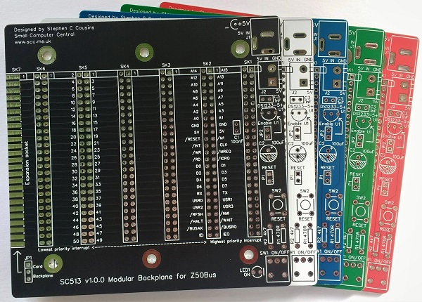
SC513 is a modular backplane designed for Z50Bus.
Documentation
- SC500 – Series Information
- SC513 – Description
- SC513 – Assembly Guide
- SC513 – Parts List
- SC513 – Printed Circuit Board
- SC513 – Support
- SC513 – User Guide
Downloads
Kits
Description
SC513 is a modular backplane designed for the Z50Bus.
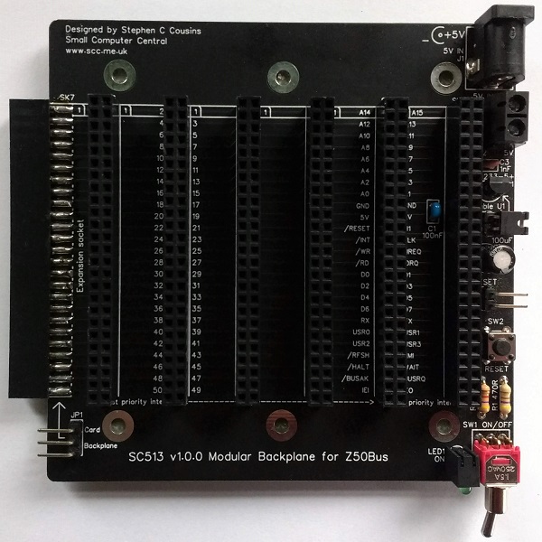
The backplane offers 6 vertical Z50Bus sockets and 1 horizontal Z50Bus socket. It also has a 5-volt power input with an on/off switch, a voltage supervisor and reset device, a power indicator, and a reset button.
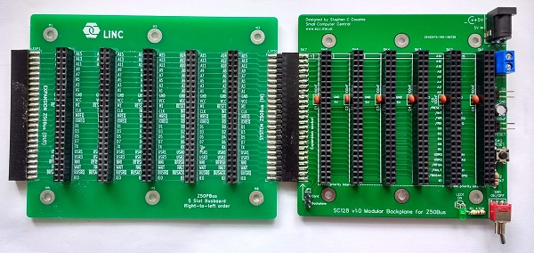
The backplane is a modular design allowing it to be extended using the LiNC 5-slot backplane.
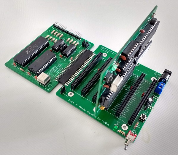
Alternatively, the horizontal socket can be used to connect a Z50Bus card. This can be very useful when debugging hardware.
Parts List
| Reference | Qty | Component |
| PCB | 1 | SC513, v1.0, PCB |
| C1 | 1 | Capacitor, ceramic, 100 nF |
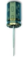
| C2 | 1 | Capacitor, electrolytic, 100 µF |
| C3 | 1 | Capacitor, ceramic, 1 nF |
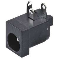
| J1 | 1 | Socket, power, barrel, 2.1mm |
| J2 | 1 | Screw terminal, 2 way, 5.0mm pitch |
| JP1 | 1 | Header, male, 1 row x 3 pin, angled |
| JP2 | 1 | Header, male, 1 row x 2 pin, angled |
| Jumper shunt | 2 | Jumper shunt |
| LED1 | 1 | LED, green, 3mm, angled |
| P1 | 1 | Header, male, 1 row x 2 pin, angled |
| R1 | 1 | Resistor, 470R, 0.25W |
| R2 | 1 | Resistor, 4k7, 0.25W |
| SK1 to SK7 | 7 | Header, female, 2 row x 25 pin, straight |
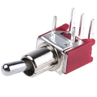
| SW1 | 1 | Switch, toggle, sub-miniature, SPDT |
| SW2 | 1 | Switch, tactile button |
| U1 | 1 | DS1233-5+ supervisor |
| Feet | 6 | Self-adhesive feet, or Other PCB support |
Printed Circuit Board
| Supplier | Website | Ships from |
| Stephen C Cousins | Tindie | UK |
| pcb4diy | pcb4diy.de | Germany |
| pcb4diy | eBay | Germany |
User Guide
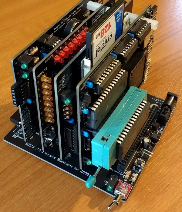
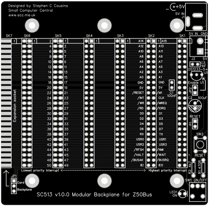
The backplane has 6 vertical sockets for Z50Bus compatible cards. It also has one horizontal socket to allow a modular backplane extension section to be connected. Alternatively, a horizontally mounted Z50Bus compatible card can be connected.
Power is supplied to the backplane from either the barrel socket or the screw terminals. This needs to be 5-volts (4.75 to 5.25 volts) at typically a few hundred milliamperes.
The backplane includes a voltage supervisor and reset device (U1). This device will hold the system in reset if the supply voltage is below approximately 4.75 volts. If the system does not start, always check the reset signal is not being held low and also that the supply voltage reaching the backplane is at least 4.75 volts.
The only complication using this backplane is the Z80 mode 2 interrupt daisy chain signals, IEI and IEO.
The interrupt daisy chain consists of a signal that connects the output of one card (IEO) to the input of the next (IEI). The position of a card in the chain (ie. its position on the backplane) determines its interrupt priority. If you are using this feature you must not leave a gap between cards that support interrupts, as this will break the chain.
If you are using mode 2 interrupts and you have either a backplane section or a Z50Bus card fitted to the horizontal bus socket (SK7) then you need to fit a jumper shunt to JP1. This jumper has one position for a backplane section and another for a Z50Bus card.
One thing worth noting is that the ON/OFF switch only turns the system on and off if it is powered from the 5-volt input connectors on the backplane. If power is introduced from a Z50Bus card, such as a serial port, the switch will only isolate power from the power connectors on the backplane. not from the cards connected to the backplane.
The backplane is a modular design allowing it to be extended using the LiNC 5-slot backplane section.
Alternatively, the horizontal socket can be used to connect a Z50Bus card. This can be very useful when debugging hardware.
Assembly Guide
Experienced builders:
Please read the warning about capacitor C2. Other than that there shouldn’t be any other surprises to catch you out.
This guide assumes you are familiar with assembling circuit boards, soldering, and cleaning. If not, it is recommended you read some of the guides on the internet before continuing.
First check you have all the required components, as listed in the parts list.
Before assembling it is worth visually inspecting the circuit board for anything that looks out of place, such as mechanical damage or apparent manufacturing defects.
If you have a multimeter that measures resistance or has a continuity test function, check there is not a short on the power supply tracks. Connect the probes to each terminal of one of the capacitors, such as C1. This should be an open circuit, not a short.
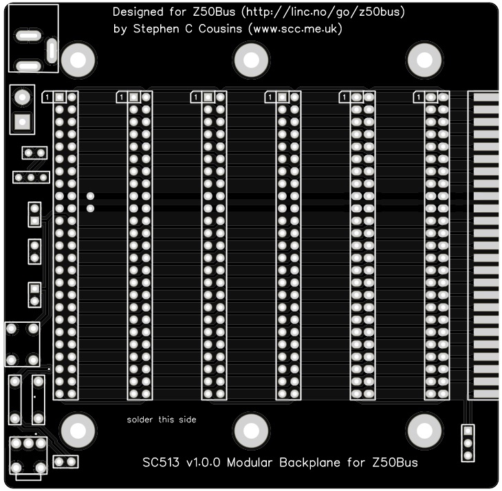
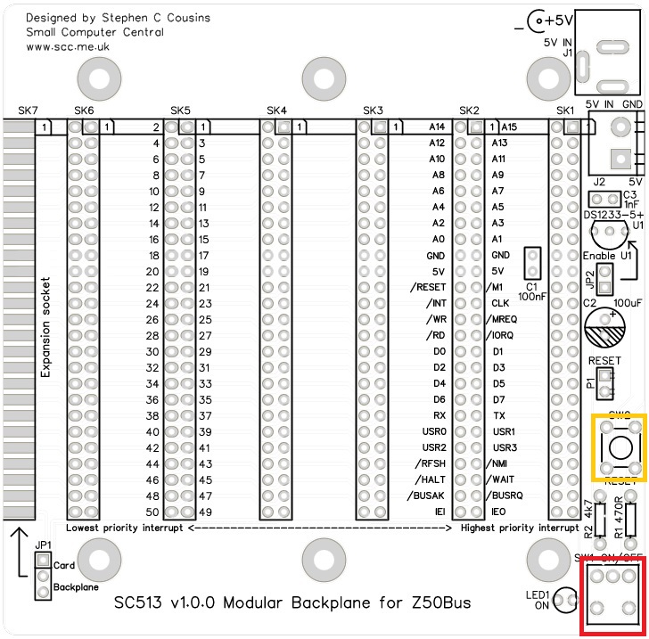
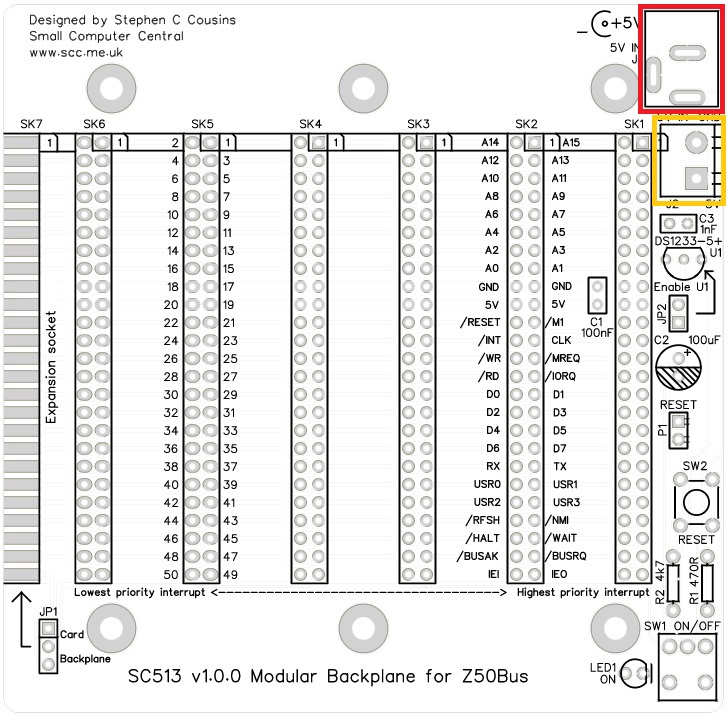
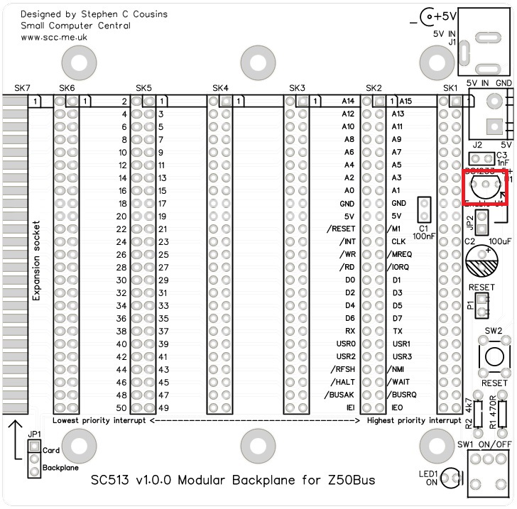
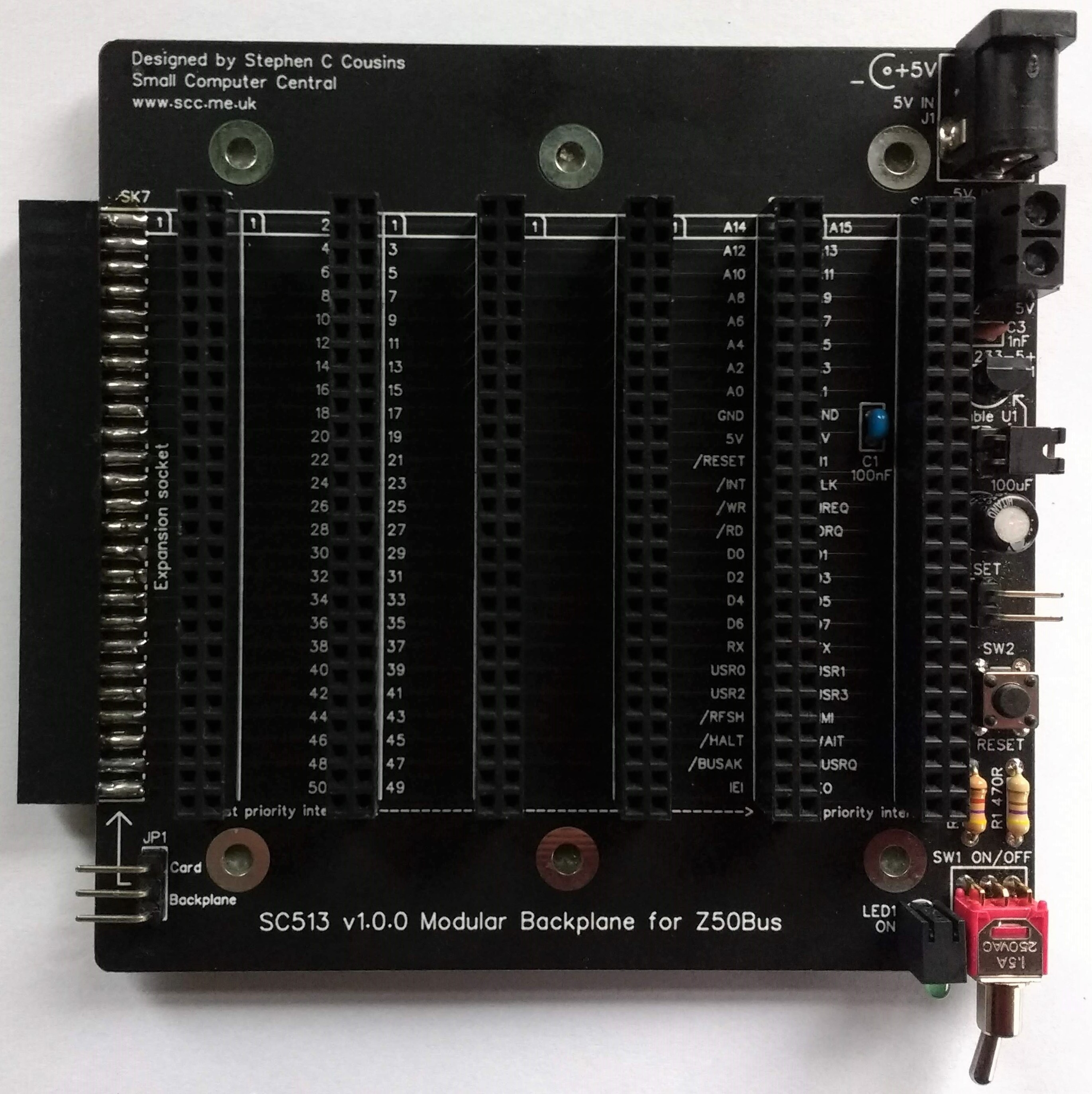
The picture below shows what a completed SC513 should look like.
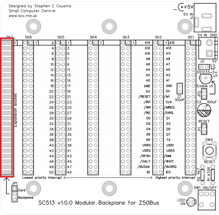
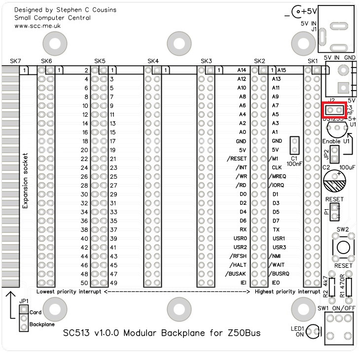
Horizontal header socket
Fit and solder the header socket, SK7, in the position indicated below in yellow.

Press the connector firmly against the edge of the PCB and ensure the pins are in the centre of the pads. Solder one of the middle pins on one side of the board and then check the connector is still in the correct place and the socket is parallel to the board’s surface.
Solder one of the middle pins on the other side of the board and repeat the checks. It is important the socket is parallel to the PCB so any backplane extension section or Z50Bus card is neatly aligned with the SC513 PCB.
Solder one pin at each end of the connector and on each side of the board. Repeat the alignment checks. Now solder all the remaining pins.
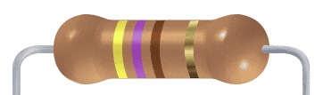
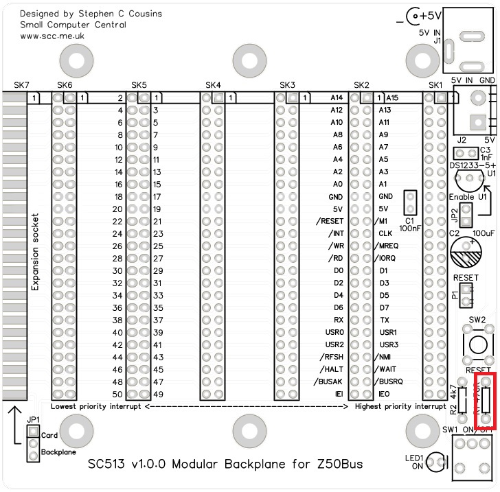
Resistor 470R
Fit and solder the 470R resistor, R1.
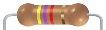
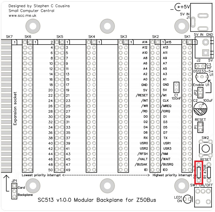
Resistor 4k7
Fit and solder the 4k7 resistor, R2.
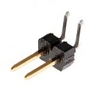
Header pins (2 pin)
Fit and solder header pins, P1 and JP2.
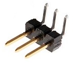
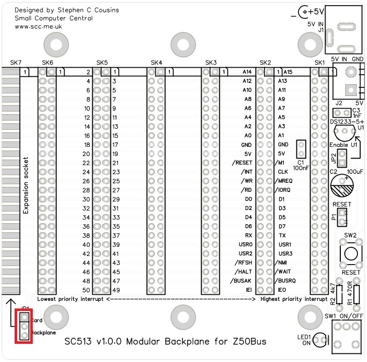
Header pins (3 pin)
Fit and solder the header pins, JP1.
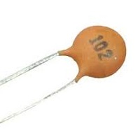
Capacitor (100 nF)
Fit and solder the 100 nF cacacitor, C1.
This capacitor can be fitted either way around, as it is not polarity dependent.
The exact value of this component is not critical. The use of very cheap capacitors within the range of about 30 to 200 nF is acceptable.

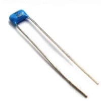
Capacitor (1 nF)
Fit and solder 1 nF ceramic capacitor, C3.
These capacitors can be fitted either way around, as they are not polarity dependent.
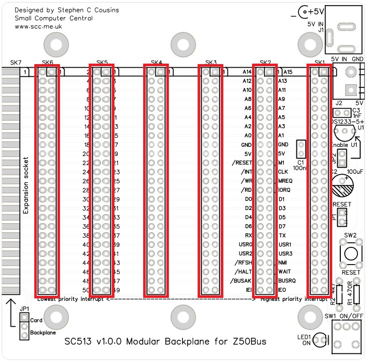
Header sockets
Fit and solder the header sockets, SK1 to SK6.
Capacitor (100 µF)
Fit and solder capacitor, C2.
It is important to fit this capacitor the right way around. The negative terminal is indicated with a ‘minus’ sign, as illustrated to the right. The negative terminal also has a shorter lead.
WARNING
PCB v1.0.0: Do not fit C2 tight to the PCB as it needs to be bent over slightly to allow rooms for cards with box headers. Alternatively, lay the capacitor on its side.

Switches
Fit and solder toggle switch, SW1 (shown below in red).
Fit and solder push button switch, SW2 (shown below in yellow).

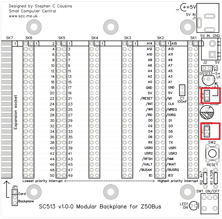
Power connectors
Fit and solder 2.1 mm barrel power socket, J1 (shown below in red).
Fit and solder screw terminal, J2 (shown below in yellow).

Light Emitting Diodes (LED)
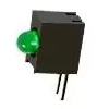
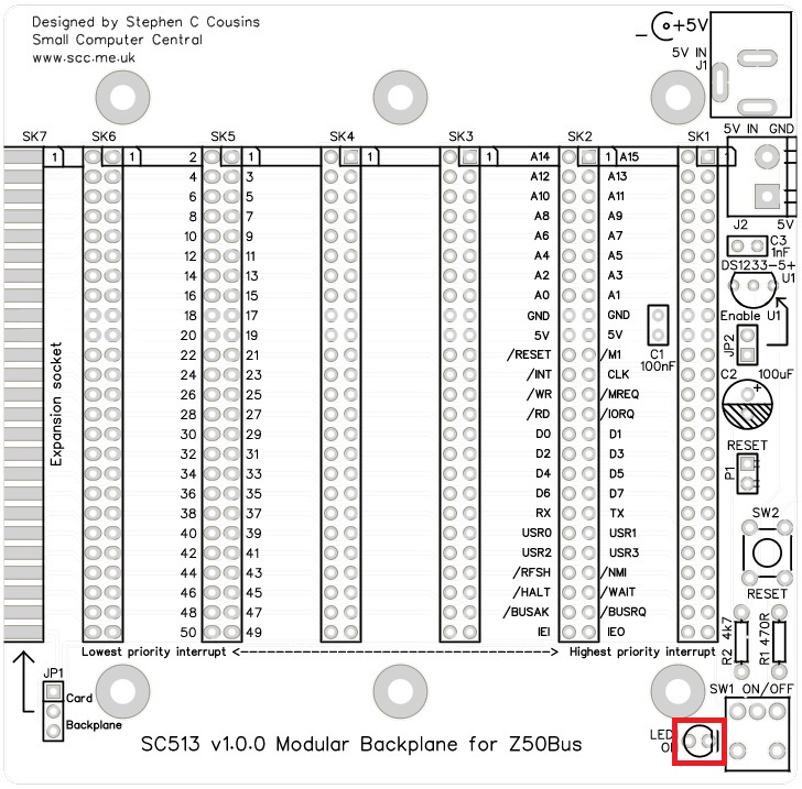
Fit and solder green LED (LED1) in the position shown below.
If using an angled LED the polarity is predefined and matches the PCB.
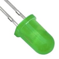
If using standard LEDs care must be taken to ensure they are fitted the correct way around.
It is important to fit the LED the correct way around. LEDs usually have a small flat side to indicate the cathode (the negative end). This should be positioned to match the flat side shown on the circuit board (illustrated to the right). Also, the cathode pin on the LED is usually shorter than the other pin (the Anode).

Voltage supervisor and reset
Fit and solder the DS1233 voltage supervisor and reset device, U1.
This device must be fitted the correct way around. Match the shape of the device to the legend on the circuit board.
It is necessary to spread the legs of the device to match the hole spacing on the circuit board. Do this gently so as to avoid straining the legs where they enter the plastic casing. DO not press the component hard into the board as this will also strain the legs.
Testing
Visually inspect all soldering for bad joints and for shorts. Clean the flux from the board and visually inspect again.
Check there is not a short on the circuit board’s 5 volt supply by connecting the multimeter’s probes to each terminal of the screw terminal block (J2). This should read an open circuit, not a short. Test with the toggle switch in both positions.
If you really want to play safe you can use the multimeter to check for a short between all adjacent pins on the backplane. You could also check for continuity between all the pins on the same backplane signal line. Note that signals IEI and IEO form a daisy chain so do not simply connect straight through to each socket, as all the other signals do. This level of checking is very tedious and unlikely to find a problem if you have thoroughly inspected the soldering with a magnifying glass.
Connect a 5 volt supply to the screw terminals (J2) or the barrel socket (J1). The power LED should light when the toggle switch is in the ON position – the toggle switch pointing away from the LED.
Disconnect the power supply and connect a minimal set of Z50Bus cards to the backplane. Power up and check the system is running. If all is well, fit any other Z50Bus cards and turn off your soldering iron!
Notes
- This design is made with the permission of LiNC (designers of the Z50Bus).
- This product is designed for hobby use and is not suitable for industrial, commercial, or safety-critical applications.
- The product contains small parts and is not suitable for young children.
