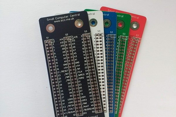
SC507 is a 3-slot backplane designed for Z50Bus.

- SC500 – Series Information
- SC507 – Description
- SC507 – Assembly Guide
- SC507 – Parts List
- SC507 – Printed Circuit Board
- SC507 – Support
- SC507 – User Guide
Downloads
Kits
Description
SC507 is a 3-slot backplane designed for Z50Bus.

SC507 has three Z50Bus sockets, with narrow (0.6″) spacing, making it suitable for use in a very compact system.
Backplanes with narrow slot spacing (eg. 0.6″) are best suited to building compact systems, while wide slot spacing (eg. 0.8″) is more convenient when experimenting and developing hardware.
The main features of this design are:
- Three Z50Bus sockets
- Simple passive design
- Compact 0.6″ (15.24mm) slot spacing
Parts List
| Reference | Qty | Component |
| PCB | 1 | SC507, v1.0, PCB |
| S1 to S3 | 3 | Header, female, 2 x 25 pin, straight |
| Feet | 4 | Self-adhesive feet, or Other PCB support |
Printed Circuit Board
| Supplier | Website | Ships from |
| Stephen C Cousins | Tindie | UK |
| pcb4diy | pcb4diy.de | Germany |
| pcb4diy | eBay | Germany |
User Guide
SC507 is a 3-slot backplane designed for Z50Bus.
Cards can be placed in any socket, the position and order does not usually matter. However, there are a few exceptions.
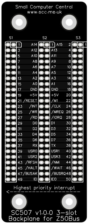
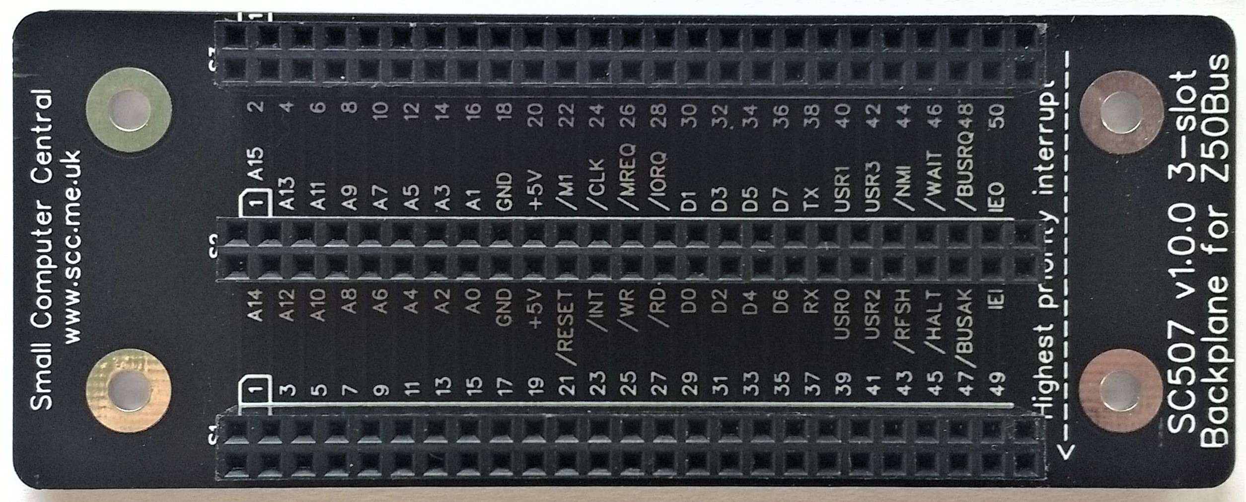
- Cards using Z80 mode 2 interrupts need to be grouped together with the highest priority interrupting device to the left (as illustrated above). These cards are linked by a daisy-chain which is incorporated into the backplane. As a result you must not leave an empty slot between any cards generating interrupts.
- Simple Compact Flash storage cards that essentially connect directly to the processor bus sometimes need to be in a socket near to the processor or they can be unreliable.
Assembly Guide
Experienced builders can just go ahead and populate the board. There shouldn’t be any surprises to catch you out.
This guide assumes you are familiar with assembling circuit boards, soldering, and cleaning. If not, it is recommended you read some of the guides on the internet before continuing.
First check you have all the required components, as listed in the parts list.
Before assembling it is worth visually inspecting the circuit board for anything that looks out of place, such as mechanical damage or apparent manufacturing defects.
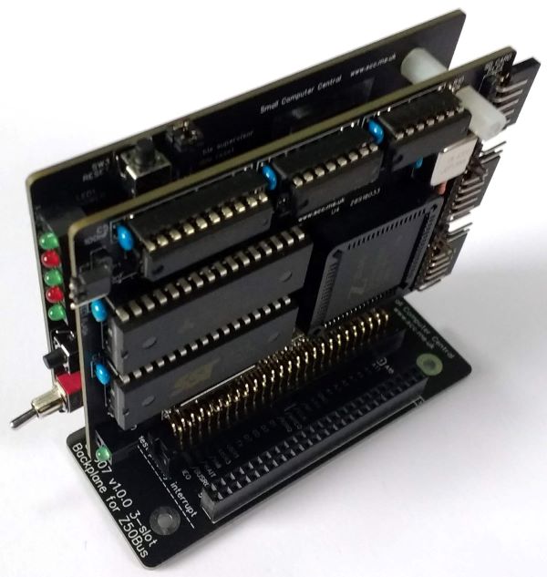
The picture below shows what a completed SC507, 3-slot backplane should look like.

Bus sockets
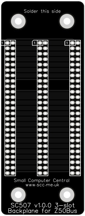
Fit and solder the 3 bus sockets (2 row x 25 pin, female) S1 to S3 (shown below in red).


Testing
Before fitting cards to the backplane, always thoroughly inspect the board for poor solder joints and for shorts between pins. The importance of visual inspection can not be over stated.
You could use a continuity tester to check for continuity and shorts, but if you thoroughly inspect the board there shouldn’t be any problems.
PCB supports
If you wish to use the backplane exposed on a desk it is recommended that some form of supports are fitted to raise and support the backplane. This can be something as simple as small self-adhesive feet stuck on the bottom of the board over the mounting holes. Alternatively, nuts and bolts could be used, or some other form of mounting.
When mounting in a case the M3 (3 mm diameter) fixing holes can be used with suitable fixings.
Notes
- This design is made with the permission of LiNC (designers of the Z50Bus).
- This product is designed for hobby use and is not suitable for industrial, commercial, or safety-critical applications.
- The product contains small parts and is not suitable for young children.
- RomWBW has been provided free of charge by its author Wayne Warthen.
