Click here for a list of the parts required to build an SC131, v1.0, pocket-sized Z180 computer.
This design is not recommended for those with very little experience of building electronics.
Experienced builders need to read the section below titled “Notes to read before you start.”
Introduction
This guide assumes you are familiar with assembling circuit boards, soldering, and cleaning. If not, it is recommended you read some of the guides on the internet before continuing.
First check you have all the required components, as listed in the parts list.
Before assembling it is worth visually inspecting the circuit board for anything that looks out of place, such as mechanical damage or apparent manufacturing defects.
If you have a multimeter that measures resistance or has a continuity test function, check there is not a short on the power supply tracks. Connect the probes to each terminal of one of the capacitors, such as C1. This should be an open circuit, not a short.
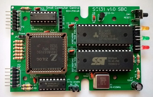
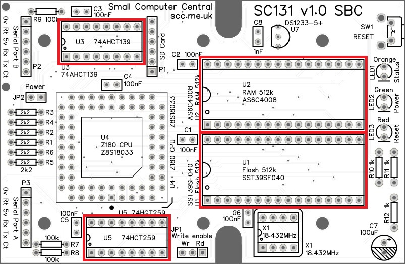
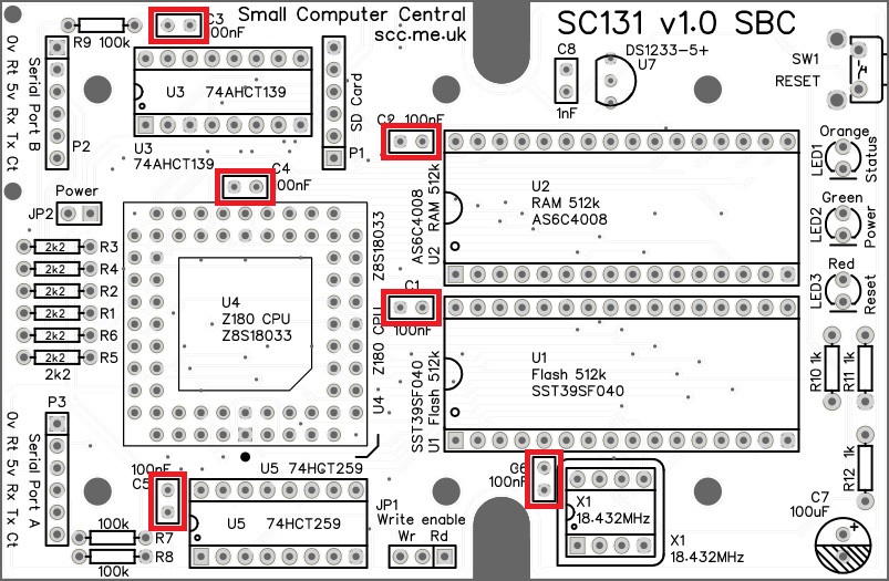
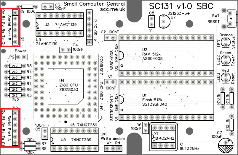
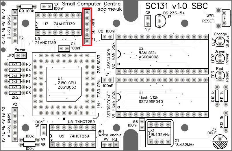
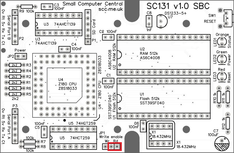
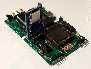
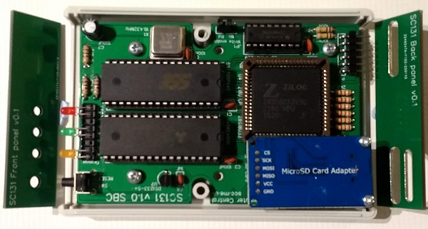
The picture below shows what a completed SC131 main circuit board should look like.
Notes to read before you start
Experienced builders should read these notes, the section about component forming, the section about the Micro SD adapter, and the section about modifying the case. After that you can go ahead and populate the board without studying every detail of this guide.
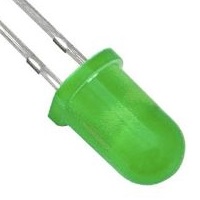
The brightness of the green LED in the kit is less than the other two. The green LED is on all the time the system is powered, whilst the other two only come on to indicate specific states. The green LED is not so bright it is distracting, while the other two are bright enough to be easily noticed. If you want the green LED to be brighter you can replace the 1k resistor R11 with a 470 ohm or even a 330 ohm resistor. Personally, I would not do this as I find having a bright LED on all the time is annoying .
Component forming
Before starting assembly there are a few components that need forming.
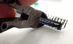
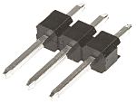
Headers P2 and P3 are made from a double row angled male header.
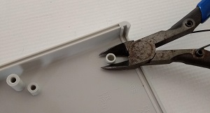
If the header strip is longer than 6 pins, first cut off two sections of 2 rows by 6 pins each. A pair of long nose cutters works well here.
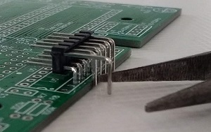
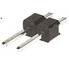
Press the header onto the edge of the SC131 main PCB at U5, as shown to the right, and pull out the top row of pins with a pair of pliers.
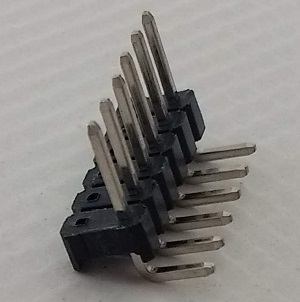
You should end up with two headers that look like the picture to the right.
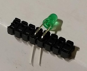
The LED legs need to be bent 90 degrees.
Remove all the pins from a third section of double row header. This section should be eight pins long. A suitable header is supplied in the SC131 component kit.
Use this as a guide to bend the LED legs to 90 degrees, as shown. Note very carefully the length of the leads on the LED. One is longer than the other. It is vital they are the right way around.
Use this method to form the leads on each of the three LEDs.
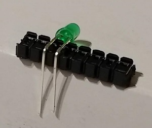
Later this piece of plastic will be used as a spacer for the LEDs, as shown below.
Component details and sourcing
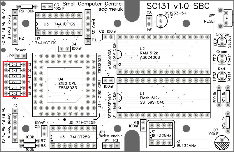
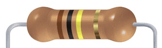
Resistors 2k2
Fit and solder the 2k2 resistors R1 to R6 (shown below in red).

These can be fitted either way around, as they are not polarity dependent. However, the board will look nicer if they are all the same way around.
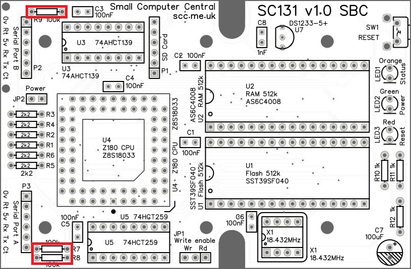
Resistors 100k
Fit and solder the 100k resistors R7 to R9.
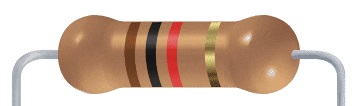
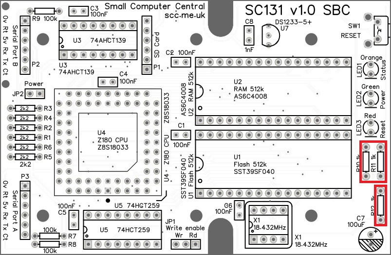
Resistor 1k
Fit and solder the 1k resistors R10 to R12.
IC sockets
Fit and solder the IC sockets.
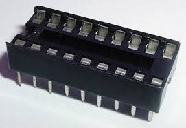
Be sure to fit them with the notch matching the legend on the circuit board, so you do not end up fitting the IC the wrong way around too.

PLCC socket
Fit and solder the 68-pin PLCC socket for U4.
This type of socket can be difficult to insert into the PCB holes as there are so many fragile pins, which must be carefully aligned.
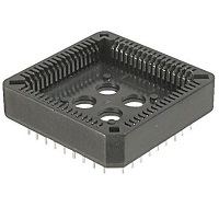
It is vital this socket is fitted the correct way around. The socket has a small chamfer on one corner, as indicated below in green.

Quick Test
It is now worth repeating the check made earlier for a short on the power supply tracks. Connect the meter probes to each terminal of one of the capacitors, such as C1. This should be an open circuit, not a short.
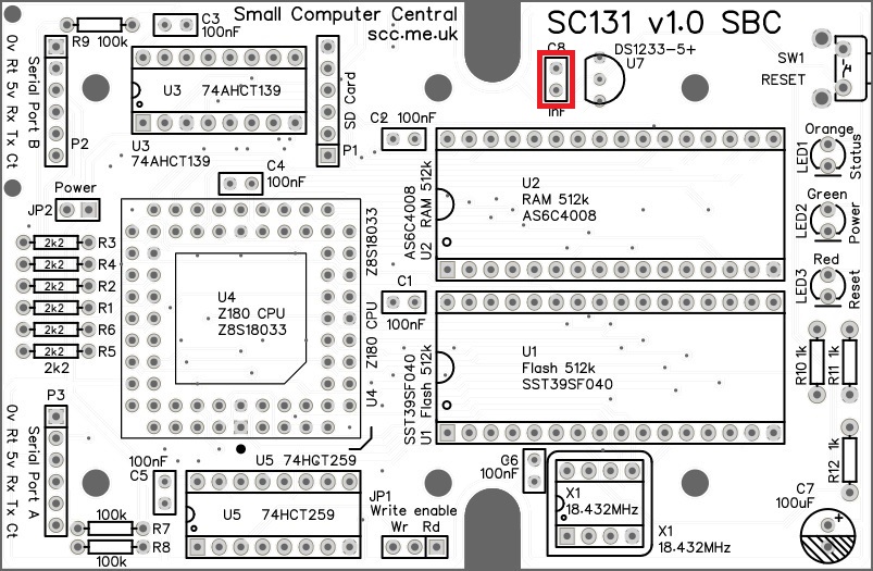
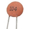
Capacitor (1 nF)
Fit and solder capacitor C8.

This capacitor can be fitted either way around, as it is not polarity dependent.
The exact value of this component is not critical. The datasheet for the DS1233 specifies a value from 0.5 to 10 nF, thus a very low cost component with a wide tolerance is acceptable.
Capacitors 100 nF
Fit and solder capacitors C1 to C6.
These capacitors can be fitted either way around, as they are not polarity dependent.
The exact value of this component is not critical. The use of very cheap capacitors within the range of about 50 to 150 nF is acceptable.
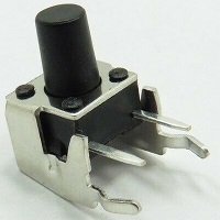
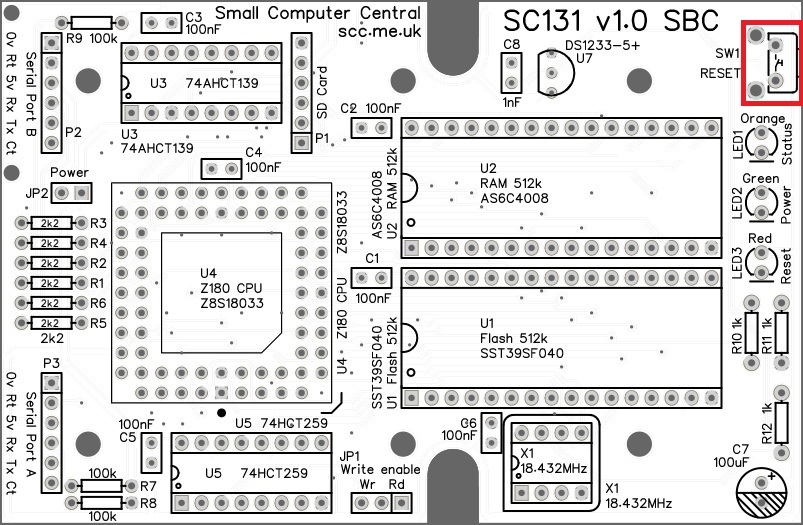
Reset button
Fit and solder push button switch SW1.
It is important for alignment with the front panel that this switch is pressed firmly against the PCB when soldering.
Quick Test
Again, repeat the check made earlier for a short on the power supply tracks. Connect the meter probes to IC U5 pin 16 (shown below in red) and U5 pin 8 (shown in green). This should be an open circuit, not a short. If you are using a digital meter set to measure resistance it will likely take a few seconds for the reading to stabilise as there are now capacitors on the power lines. A reading of more than 100 kΩ (100000 ohms) is acceptable.
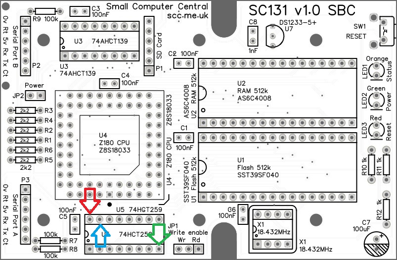
Measure the resistance between IC U5 pin 8 (green) and U5 pin 15 (blue). This is measuring the resistance of the reset switch (SW1). It should currently be open circuit. Again, the reading may take a few seconds to stabilise. A reading of more than 100 kΩ (100000 ohms) is acceptable. Whilst still measuring the resistance, press the reset button. The reading should now be a short circuit. A reading of less than 1 Ω is ideal, but less than 10 Ω is acceptable. The 10 ohm limit has been suggested mainly to allow for measurement accuracy with cheap meters.
Headers (angled)
Fit and solder the pin headers P2 and P3 (1 row of 6 pins).
Ensure the pins are parallel to the circuit board. This is important for alignment with the back panel.
Headers (straight)
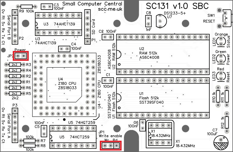
Fit and solder the pin header JP1 (1 row of 3 pins).
Fit and solder the pin header JP2 (1 row of 2 pins).
These may need to be cut from longer strips using wire cutters to cut the plastic.
Micro SD card adapter
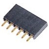
Fit and solder the header socket P1 (1 row by 6 pin).
It is important this socket is pressed firm against the PCB when soldering.
Capacitor (100 µF)
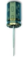
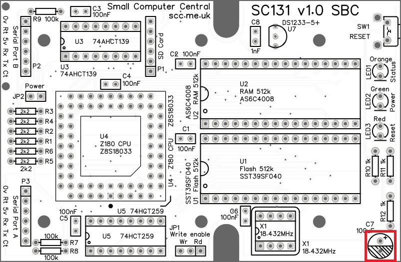
Fit and solder capacitor C7.
It is important to fit this capacitor the right way around. The negative terminal is indicated with a ‘minus’ sign, as illustrated to the right. The negative terminal also has a shorter lead.
LEDs
Fit and solder the LEDs (LED1 to LED3) in the position shown below.
It is important to fit the LED the correct way around. LEDs usually have a small flat side to indicate the cathode (the negative end). This should be positioned to match the flat side shown on the circuit board (illustrated to the right). Also, the cathode pin on the LED is usually shorter than the other pin (the Anode).
The plastic strip used to form the LEDs is now used as a spacer, as illustrated to the right.


Quick Tests
Repeat the check made earlier for a short on the power supply tracks. Connect the meter probes to IC U5 pin 16 (shown below in red) and U5 pin 8 (shown in green). This should be an open circuit, not a short. If you are using a digital meter set to measure resistance it will likely take a few seconds for the reading to stabilise as there are now capacitors on the power lines. A reading of more than 100k Ω (100000 ohms) is acceptable.
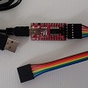
Connect an FTDI style serial adapter to serial port A and power the adapter by plugging is in to a USB socket. A typical FTDI style adapter and cables is illustrated to the right.
- The green “Power” LED should be on.
- The red “Reset” LED should light when you press the reset button.
- The orange “Status” LED should light when you connect U5 pin 5 to U5 pin 8 with a piece of wire.
- The voltage between IC U5 pin 16 and U5 pin 8, should be between 4.75 and 5.25 volts.
- The voltage between U1 pin 31 (WR to Flash) and U5 pin 8 is below 0.5 volts but rises to above 4.5 volts when a jumper shunt is fitted to the read only “Rd” position of JP1. Without the shunt fitted the signal is floating, so with a digital meter it may not be stable but should be below 0.5 volts.
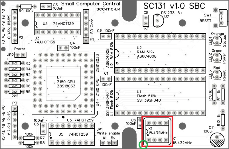
Oscillator (18.432 MHz)
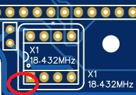
Fit and solder the 18.432 MHz oscillator, X1. Be sure to fit it the correct way around.
Pin 1 of the oscillator is normally indicated by a ‘sharp’ corner, while the other three corners are rounded.
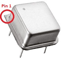
Pin 1 on the circuit board is also indicated by a ‘sharp’ corner, while the other three corners are rounded.
Voltage supervisor and reset
Fit and solder the DS1233 voltage supervisor and reset device U7.
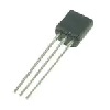
This device must be fitted the correct way around. Match the shape of the device to the legend on the circuit board.
It is necessary to spread the legs of the device to match the hole spacing on the circuit board. Do this gently so as too avoid straining the legs where they enter the plastic casing. Do not press the component hard into the board as this will also strain the legs.
Inspection
Remove any solder ‘splats’ with a brush, such as an old toothbrush.
Visually inspect the soldering for dry joints and shorts.
Clean the flux off with suitable cleaning materials.
Visually inspect again.
Quick Test
Connect an FTDI style serial adapter to serial port A and power the adapter by plugging it in to a USB socket. The red “Reset” LED should come on for about half a second when power is applied.
Check the red “Reset” LED comes on for at least half a second when the reset button is pressed. It should stay on when the button is held in and stay on for about half a second after the button is released.
If the red “Reset” LED stays on, it is most likely the supply voltage is less than the voltage supervisor (U7) accepts as adequate (that’s about 4.7 volts). This results in the reset signal being held low and thus the reset LED is on. The voltage supervisor’s threshold voltage varies a little with device tolerances, but it should trip between 4.5 and 4.75 volts.
It is vital the USB serial adapter is able to supply an adequate voltage to the circuit board. Even some branded models will not do this. Many USB cables will cause a significant voltage drop when even low currents are drawn.
Integrated Circuits
If all the above tests check out okay, disconnect the power and insert the integrated circuits into their sockets.
Fit the Z180 CPU into its socket as illustrated to the right. This must be fitted the correct way around. The socket and IC both have a small chamfer in the position indicated.
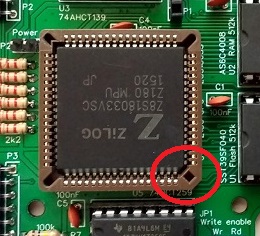
Take care to insert the Z180 CPU level. Avoid pressing one side in while the other side is still raised. If you need to remove the IC it is worth getting a special tool which hooks under opposite corners of component so that it can be lifted out evenly.
Fit a jumper shunt in the positions shown below.
Initial Testing
Connect an FTDI style serial adapter to serial port A and power the adapter by plugging is in to a USB socket.
The green “Power” LED should be on all the time power is applied.
The red “Reset” LED should come on for about half a second when power is applied, then go off.
With the current firmware, the orange “Status” LED should light for about half a second, then pulse off for a fraction of a second, then come back on. The orange LED’s activity is showing the firmware’s initialisation and self-test.
When the reset button is pressed (and released) the LEDs should show similar activity as they do following power-up.
An FTDI style serial adapter and cable is typically used to connect to the computer, as illustrated to the right.
The terminal software should be set for 115200 baud, 8 data bits, no parity, 1 stop bit, and hardware flow control disabled (for this initial test). Power up and you should see the startup message.
Given that the self-test passed, a failure to display the start up message is most likely to be directly related to the serial port electronics or the serial adapter cable. Check for activity at the serial port connector and around the 2k2 resistors.
If all is well set the terminal software to use hardware flow control and check you still see the startup message. It is recommended that hardware flow control be used where possible.
If you have further problem the SC131 troubleshooting guide may help.
Micro SD card adapter
Before fitting the Micro SD card adapter it should be given a quick test.
Power down and connect the Micro SD card adapter, as shown to the right. Insert a Micro SD card.
Power up and check the Micro SD card is identified. RomWBW should list the presence of the card in the start-up text.
Power down and remove the Micro SD card and also disconnect the Micro SD card adapter.
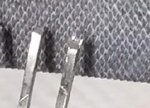
The Micro SD card adapter needs to have its pins straightened so they stand vertical with respect to the PCB.
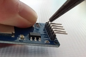
Plug the adapter into the main SC131 circuit board.
Notice that the pins are too long – you can see the metal pins. Disconnect the adapter and cut the pins down in length so that the adapter fits tightly down onto the socket. Take your time here to avoid cutting too much off. It is best to use an old pair of cutters as the pins are quite hard.
Also, the burrs on the pins should be filed off before plugging into the socket. Filing the burrs off reduces the wear on the socket when the adapter is pushed in.
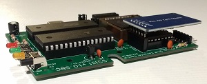

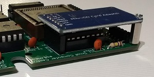
Fit the Micro SD module to the main PCB using two standoff pillars and four screws.
The Micro SD adapter will probably touch the top of the case and may prevent the case from closing tightly. Cutting the pins, where indicated with the red arrow, as flush to the SD adapter circuit board as possible should solve this problem.

Modifying the case
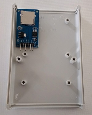
The lid of the case needs modifying to make room for the Micro SD card adapter.
The lid is the part of the case shell with the shallow rectangular recess on the outside. The base is the part with the screw holes visible from the outside.
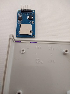
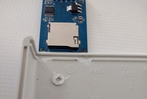
Note the orientation of the lid and the position the Micro SD adapter needs to occupy, as illustrated to the right.
Drill out the pillar, as illustrated, to remove most of the plastic. Take care not to drill right through the case!
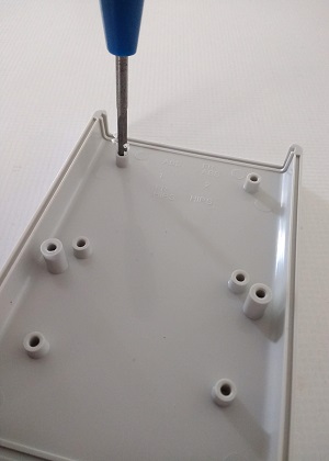
Remove the remaining plastic with cutters or a knife.
The following modification is only needed if the case does not close fully without it.
Mark the case with a felt tipped pen, as illustrated. The idea here is to mark where the screw heads holding the Micro SD adapter will touch the case.
Remove the marked area with a sharp knife. And be careful!
The final result should look like this.
Some fine tuning may be required if the lid does not fit tightly down on to the base.
Case assembly
To assemble the case and its contents, hold the front and back panels in position at each end of the main PCB and lower the three parts together into the base of the case. The base is the part with the screw holes visible from outside the case.
The main PCB can then be screwed down. Three screws is adeqate.
The top of the case (the part with the rectangular recess visible from the outside) should then be slotted on top. Check it closes down tight to the base. Also, check the reset button is reasonably centred in the hole in the front panel and check the rear panel gives clear access to the serial ports and SD card.
If it all looks good, screw the two case parts together from the underside.
You may wish to glue the LEDs to the front panel to reduce the chance of them being pushed in. The front and back panels are a loose fit so you may wish to glue them into the base part of the case. Personally, I wouldn’t do either of these as it makes dismantling difficult, should the need arise.
Getting Started
The SC131 User Guide can be found here.
Other information about SC131 can be found here.
