Click here for a list of the parts required to build an SC114, v1.0, Z80 Motherboard.
Experienced builders can just go ahead and populate the board. There shouldn’t be any surprises to catch you out.
This guide assumes you are familiar with assembling circuit boards, soldering, and cleaning. If not, it is recommended you read some of the guides on the internet before continuing.
First check you have all the required components, as listed in the parts list.
Before assembling it is worth visually inspecting the circuit board for anything that looks out of place, such as mechanical damage or apparent manufacturing defects.
If you have a multimeter that measures resistance or has a continuity test function, check there is not a short on the power supply tracks. Connect the probes to each terminal of one of the capacitors, such as C1. This should be an open circuit, not a short.
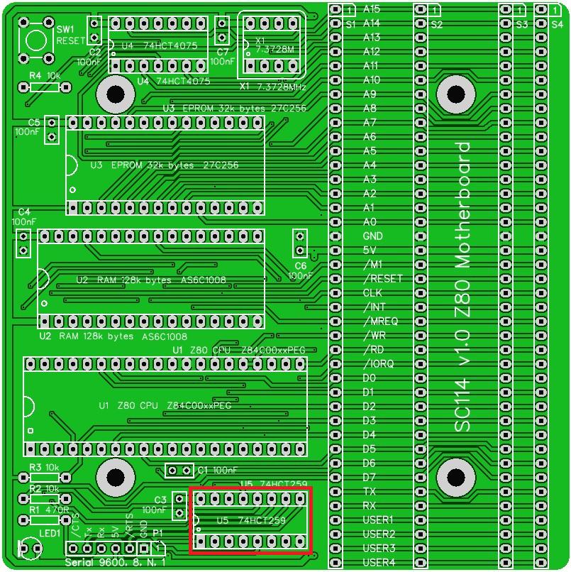
The picture below shows what a completed SC114 motherboard should look like. Note, while not very obvious from this angle, most of the integrated circuits in this example are soldered in rather than using sockets.
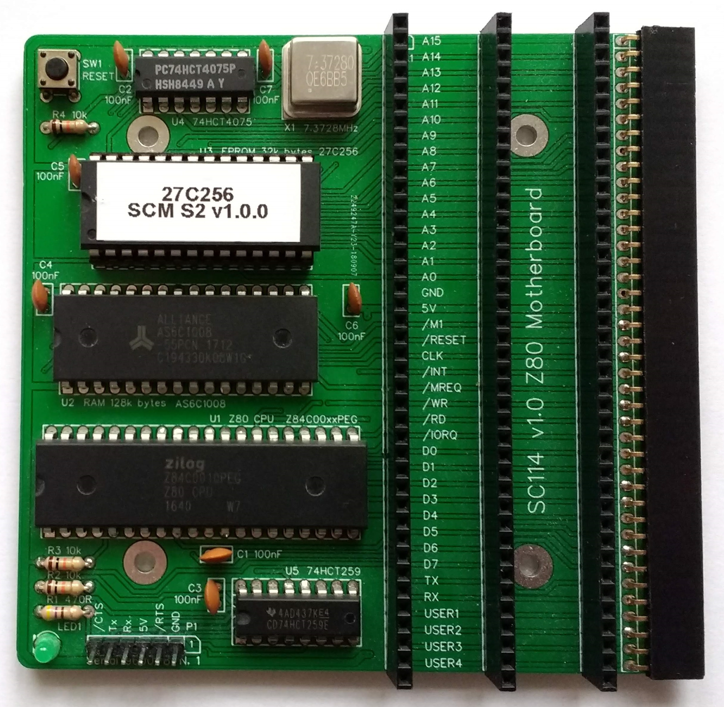
Component details and sourcing
Resistors
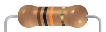
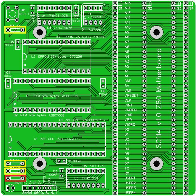
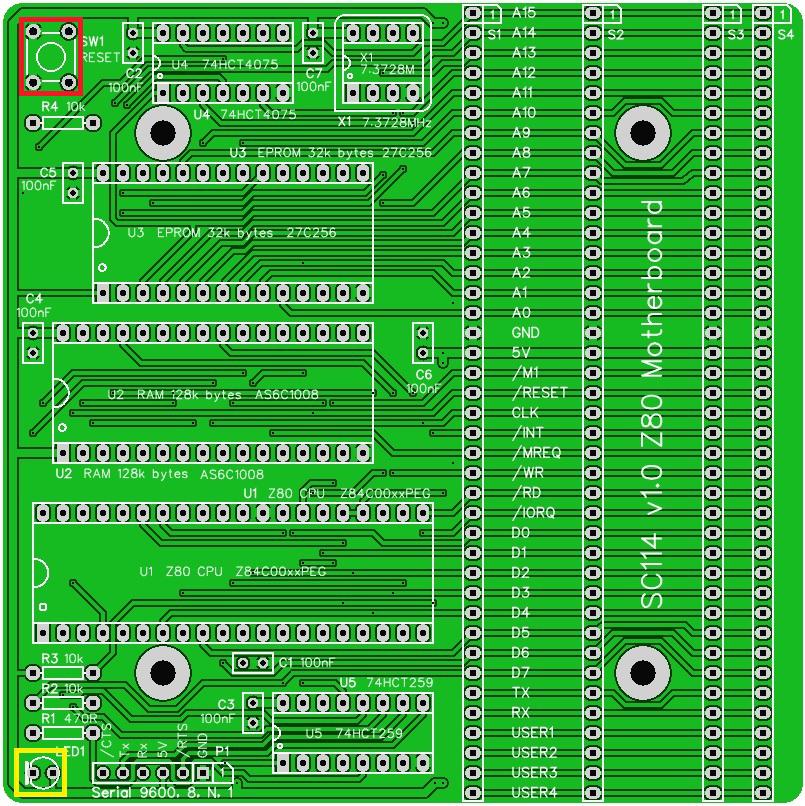
Fit and solder the 470R resistor R1 (shown in RED below).
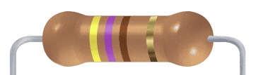
Fit and solder the three 10k resistors R2 to R4 (shown in yellow below).
IC sockets
Fit and solder IC sockets for U1 to U5.
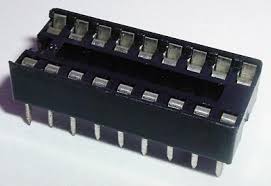
Be sure to fit them with the notch matching the legend on the circuit board, so you do not end up fitting the IC the wrong way round too.

The sockets should be fitted in the positions shown below.

Capacitors
Fit and solder capacitors C1 to C7.
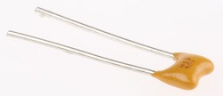
These can be fitted either way round, as they are not polarity dependent.

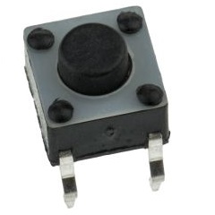
Switch and LED
Fit and solder the push button switch SW1 (shown in red below).
Fit and solder the LED (shown in yellow below).

It is important to fit the LED the correct way round. LEDs usually have a small flat side to indicate the cathode (the negative end). This should be positioned to match the flat side shown on the circuit board. Also, the cathode pin on the LED is usually shorter than the other pin (the Anode).
Oscillator
Fit and solder the 7.3727 MHz oscillator X1. You can fit a socket if you wish. My preference is to solder this component.


Serial Header
Fit and solder connector P1.
This may need to be cut down from a longer strip.
Take care to ensure the pins are perpendicular to the circuit board.

Bus Sockets
This step is not required for the motherboard to operate as a single board computer. You may wish to skip this step for now.
Fit and solder connector S1 to S3 (shown in red below).
Fit and solder connector S4 (shown in yellow below).

Inspection
Remove any solder ‘splats’ with a brush, such as an old toothbrush.
Visually inspect the soldering for dry joints and shorts.
Clean the flux off with suitable cleaning materials.
Visually inspect again.
With a suitable FTDI style TTL level serial to USB adapter connected from P1 to a powered USB socket, check the supply voltage on this circuit board between U4 pin 7 and U4 pin 14. This should be 4.5 to 5.5 volts, preferably 4.75 to 5.25 volts.
Integrated Circuit U5
Insert the IC U5 (74HCT259) into its socket, taking care to insert it the right way round, as illustrated below. Be careful not to bend any legs over.

Test
With a suitable FTDI style TTL level serial to USB adapter connected from P1 to a powered USB socket, check the LED lights. If not then follow these steps.
- Check the supply voltage between U5 pin 8 and U5 pin 16. This should be 4.5 to 5.5 volts, preferably 4.75 to 5.25 volts.
- Check the LED is the correct way round.
- Check the RESET signal is high but goes low when the reset button is pressed. The LED should light when U5 is powered and working, and the RESET signal on U5 pin 15 is low. With the other ICs not fitted the LED may not stay on after the RESET signal goes high.
Do not continue assembly until the LED is working.
Integrated Circuits
Insert the ICs into their sockets, taking care to insert them the right way round, as illustrated below. Be careful not to bend any legs over.


Quick Start Guide
Below is a very brief guide to getting started with the Z80 motherboard (SC114). For further details so the SC114 User Guide.
It is assumed the Z80 motherboard is fully assembled, but no modules are fitted in the RC2014 bus sockets. The ROM should contain the Small Computer Monitor v1.0 configuration S2.
Connect a suitable FTDI style TTL level serial to USB adapter from P1 to a powered USB socket on a PC (or similar). These adapters come in many different shapes and sizes. The picture below shows one possible configuration.

Press the reset button and check the LED lights. It should flash off and on again either once or twice as previously described.
Start a suitable terminal emulation program, such as Tera Term, on the PC. Configure the PC’s serial port for 9600 baud, 8 data bits, 1 stop bit, no parity and hardware flow control (RTS/CTS).
Press the reset button on the Z80 motherboard. You should see the terminal program display something like “Small Computer Monitor – SC114”.
You are now ready to play!
Fault Finding
Check there are no chips with bent legs and thus not making contact with their socket, carefully inspect all soldering, check all the chips are inserted the right way round, check all the components are in the right place.
With a suitable FTDI style TTL level serial to USB adapter connected from P1 to a powered USB socket, check the supply voltage on this circuit board between, say, U4 pin 7 and U4 pin 14. This should be 4.5 to 5.5 volts, preferably 4.75 to 5.25 volts.
Check the LED is on. If it is not, then check the LED is the correct way round. Also check the RESET signal is high but goes low when the reset button is pressed. The LED should light when U5 is powered and working, and the RESET signal on U5 pin 15 is low.
If the LED is working, check it flashes off then on again, either once or twice after a reset. If it flashes then the motherboard is running code successfully. This would indicate that all the main components are generally working. If the LED flashes off once after reset the system has detected a serial module plugged into one of the RC2014 sockets. If it flashes off twice it has not detected a serial module and is using the onboard serial port (P1). If it keeps flashing the self-test has failed, most likely indicating the RAM is not working.
