Experienced builders can just go ahead and populate the board. There shouldn’t be any surprises to catch you out.
This guide assumes you are familiar with assembling circuit boards, soldering, and cleaning. If not, it is recommended you read some of the guides on the internet before continuing.
First check you have all the required components.
Before assembling it is worth visually inspecting the circuit board for anything that looks out of place, such as mechanical damage or apparent manufacturing defects.
If you have a multimeter that measures resistance or has a continuity test function, check there is not a short on the power supply tracks. Connect the probes to each terminal of one of the capacitors, such as C1. This should be an open circuit, not a short.
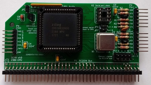
The picture below shows what a completed SC111 Z180 CPU Module should look like.
Resistors (2k2)
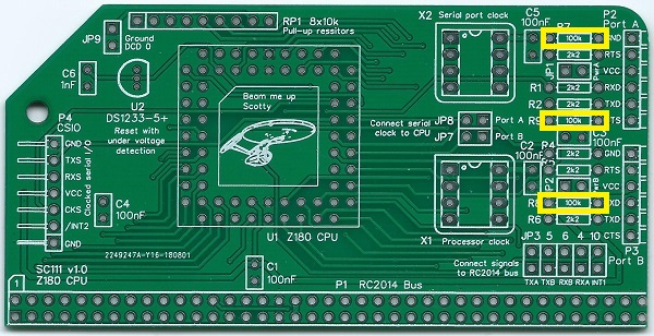
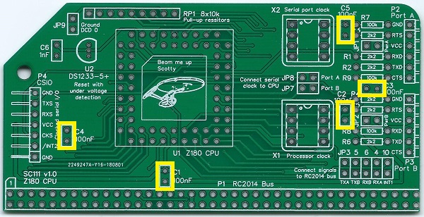
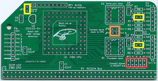
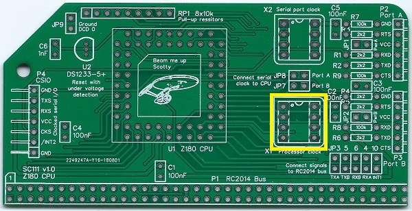
Fit and solder the 2k2 resistors R1 to R6 (shown in yellow below).
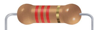
Resistors can be fitted either way round, as they are not polarity dependent.

Resistors (100k)
Fit and solder the 100k resistors R7 to R9 (shown in yellow below).
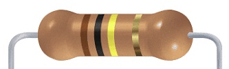
Resistors can be fitted either way round, as they are not polarity dependent.
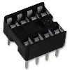
IC sockets (8-pin)
Fit and solder IC sockets for X1 and X2.
You can solder the oscillator(s) to the board instead of fitting sockets. This makes for a lower profile board, but makes changing them more difficult.
Be sure to fit them with the notch matching the legend on the circuit board, so you do not end up fitting the IC the wrong way round too.

The sockets should be fitted in the positions shown below.

IC sockets (68-pin)
Fit and solder IC socket for U1.
This type of socket can be difficult to insert into the PCB holes as there are so many fragile pins, which must be carefully aligned.
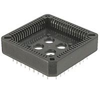
It is vital this socket is fitted the correct way round. The socket has a small chamfer on one corner, as indicated below in red.

Note, the position of the chamfered corner, illustrated below.

Capacitor (1 nF)
Fit and solder capacitor C6.

This capacitor can be fitted either way round, as it is not polarity dependent.

Capacitors (100 nF)
Fit and solder capacitors C1 to C5.
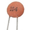
These capacitors can be fitted either way round, as they are not polarity dependent.
Bus Connector
Fit and solder bus connector P1.
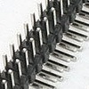
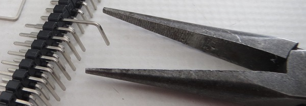
You may need to cut the connector strip to length (if starting with a strip more than 39 pins long). Long nose wire cutters snip through the plastic quite easily.
Take care to ensure the pins are parallel to the circuit board so that the board will be vertical when plugged into a backplane.
Header Pins
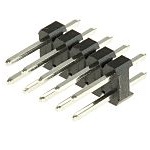
Fit and solder the right-angled male header pins, P2 and P3, shown in yellow below.
Take care to ensure the pins are parallel to the circuit board.
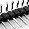
You can either fit P2 and P3 as two separate 6-pin headers, or you can fit a single 13-pin header with the middle pin removed.
Also, fit and solder the 7-pin right-angled male header pins, P4, shown in red below.

Jumper Pins
Fit and solder the jumper pins for JP1, 2 and 9. These are 1 row by 2 pin headers, shown in yellow below.
Fit and solder the jumper pins for JP 7 and 8. This is a 2 row by 2 pin header, shown in orange below.
Fit and solder jumper pins JP 3, 4, 5, 6 and 10. This is a 2 row by 5 pin header, shown in red below.


Resistor Network
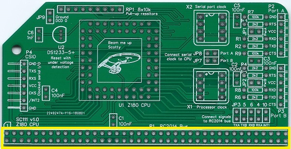
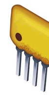
Fit and solder the 8x10k resistor network RP1.
This must be fitted the correct way round. The component should have pin 1 marked with a dot, as illustrated right.


Voltage Supervisor
Fit and solder the DS1233 voltage supervisor and reset device (U2).
This should be fitted the way round indicated by the legend on the circuit board.

Inspection
Remove any solder ‘splats’ with a brush, such as an old toothbrush.
Visually inspect the soldering for dry joints and shorts.
Clean the flux off with suitable cleaning materials.
Visually inspect again.
Before fitting the ICs, plug the board into an RC2014 backplane with no other boards fitted. Power the backplane and perform the following check with a voltmeter:
- Check the supply voltage on the module, between, say, X2 pin 8 and X2 pin 4. This should be 4.5 to 5.5 volts, preferably 4.75 to 5.25 volts.
- Check the reset signal is a logic high. With no load it should be 4.5 volts or more. This can be checked at the middle pin of the supervisor device, U2, or pin 20 of the bus connector. Some backplanes, such as SC112 and SC116, have a header for the reset signal which is easy to access. It is assumed the backplane has a pull-up resistor for the reset signal.
The reset signal should go low when the power supply voltage drops below about 4.5 volts. This indicates the voltage supervisor is working correctly.
If all is well, power down and remove the module.
Integrated Circuits
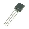
Fit the Z180 CPU into its socket as illustrated to the right.
This must be fitted the correct way round. The socket and IC both have a small chamfer in the position indicated.

Take care to insert the IC level. Avoid pressing one side in while the other side is still raised. If you need to remove the IC it is worth getting a special tool which hooks under opposite corners of component so that it can be lifted out evenly.
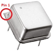
If the oscillator has not been soldered directly to the board, insert it into socket X1, as indicated below.
Pin 1 of the oscillator is normally indicated by a ‘sharp’ corner, while the other three corners are rounded.
The SC111 kit is normally supplied with an 18.432 MHz oscillator. However, other frequencies might be desirable, depending on the firmware and software you wish to run.
A socket has been provided for oscillator X2, but it is not normally required. This oscillator can be used as a clock source for the serial ports. Use of this feature will require suitable software.
Test
Fit a jumper shunt to JP9, as illustrated below in orange.
If the system is to be powered from one of the serial ports, fit a jumper shunt in one of the positions indicated in yellow below. The default port is normally port A, so JP1 is the most likely position to fit a jumper shunt.
Do not attempt to power the system from two different sources. If the system is not being powered from a serial port, then only fit a jumper shunt to JP1 or JP2 if the serial device is being powered from the system.
The block of jumpers, shown in red, only need jumper shunts fitted if you require the associated signal to be connected to the backplane.

The following assumes you are using the Z180 CPU module SC111, with the Z180 memory module SC119, and have the Small Computer Monitor, configuration S5, installed in socket U1 of this memory module. Jumper shunt JP3 of the memory module SC119 should be fitted to select Flash chip 1 (U1).
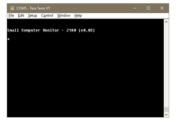
Fit these two modules to a suitable backplane. Connect an FTDI style 5 volt serial cable to the CPU module’s serial port A, with the other end connected to a computer running a terminal emulation program. The terminal should be configured for 115200 baud, 8 data, 1 stop, no parity. Flow control can be either Off, or hardware RTS/CTS.
Turn the power on to the system. The terminal should show something similar to the illustration below.