The following is a guide to getting started with RomWBW version 3.2.0.
The very latest version, source code, and documentation for RomWBW can be found here.
Getting connected
The standard distribution of RomWBW assumes a terminal (or computer running terminal software) is connected to serial port A. Typically, this is achieved with a USB to serial adapter (the small PCB shown below) either connected directly (as shown) or via a 6-way adapter cable (the multi-coloured cable shown below). The adapter is connected to the computer with a USB type A to mini-B cable.
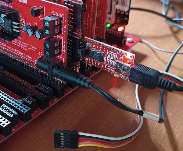
The default serial port settings are: 115200 baud, 8 data, 1 stop, no parity, RTS/CTS hardware no flow control.
A Compact Flash card is optional. If present, it should be connected via a Compact Flash module (eg. SC715).
Diagnostic display
At power-up RomWBW initialises and, if a suitable LED output module is present at I/O address 0x00, displays diagnostic information on the LEDs.
The diagnostic display should result in the LEDs each lighting in turn until all 8 are turned on. The LED display, shown in binary, goes through the following sequence:
- 0000 0000 = State after hardware reset
- Disable interrupts
- 0000 0001 = Start of initialisation
- Setup Z180 base address
- 0000 0010
- Setup Z180 registers
- 0000 0011
- Install HBIOS into RAM and transition to RAM
- 0000 0111
- Setup page zero interrupt vector
- 0000 1111
- Determine CPU type and speed
- 0001 1111
- Initialise heap storage
- 0011 1111
- Pre-console initialisation
- 0111 1111
- Output any cached debug text
- Announce HBIOS and version
- 1111 1111
- Display system information
For full details see RomWBW source code, file “hbios.asm”.
After this the startup information is sent to the terminal via the serial port.
Startup information
When RomWBW starts it will display something like this on the terminal:
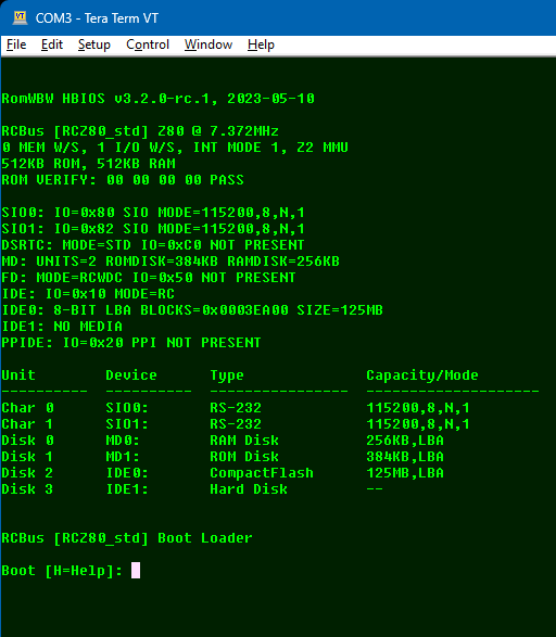
The first line shows the HBIOS version.
RomWBW HBIOS v3.2.0-rc.1, 2023-05-10
Following this is the platform name “RCBus” and the configuration name “[RCZ80_std” and the CPU details “Z80 @ 7.372MHz”.
RCBus [RCZ80_std] Z80 @ 7.372MHz
The memory and I/O wait states are shown, each with a value of 0 to 3. Zero wait states is the fastest. Several wait states are added to I/O operations to increase the access time . The interrupt mode is also shown, followed by memory size.
0 MEM W/S, 2 I/O W/S, INT MODE 2
512KB ROM, 512KB RAM
The next block is all the devices detected.
SIO0: IO=0x80 SIO MODE=115200,8,N,1
SIO1: IO=0x82 SIO MODE=115200,8,N,1
DSRTC: MODE=STD IO=0xC0 NOT PRESENT
MD: UNITS=2 ROMDISK=384KB RAMDISK=256KB
FD: MODE=RCWDC IO=0x50 NOT PRESENT
IDE: IO=0x10 MODE=RC
IDE0: 8-BIT LBA BLOCKS=0x0003EA00 SIZE=125MB
IDE1: NO MEDIA
PPIDE: IO=0x20 PPI NOT PRESENT
SIO0 and SIO1 are serial ports.
DSRTC is the Real-Time Clock. The charge must be off. This is an optional extra module.
MD is the memory device. There should be 2 units: ROMDISK and RAMDISK.
Any IDE devices detected are shown, such as Compact Flash cards.
Other optional devices are shown depending on the RomWBW configuration and the supported hardware.
Next, a list of available devices is shown.
Unit Device Type Capacity/Mode
---------- ---------- ---------------- --------------------
Char 0 SIO0: RS-232 115200,8,N,1
Char 1 SIO1: RS-232 115200,8,N,1
Disk 0 MD0: RAM Disk 256KB,LBA
Disk 1 MD1: ROM Disk 384KB,LBA
Disk 2 IDE0: CompactFlash 125MB,LBA
Disk 3 IDE1: Hard Disk --
Finally, the boot loader details and boot menu are shown.
RCBus [RCZ80_std] Boot Loader

Boot [H=Help]:
One of the boot options is “c”, to load CP/M.
Boot [H=Help]: c

Loading CP/M 2.2…

CBIOS v3.2.0-rc.1 [WBW]

Formatting RAMDISK…

Configuring Drives…

        A:=MD0:0
        B:=MD1:0
        C:=IDE0:0
        D:=IDE0:1
        E:=IDE0:2
        F:=IDE0:3
        G:=IDE0:4
        H:=IDE0:5
        I:=IDE0:6
        J:=IDE0:7

        1513 Disk Buffer Bytes Free

CP/M-80 v2.2, 54.0K TPA

B>
You are now ready to experiment with the software included in the Rom. This can be viewed with the DIR command.
B>DIR
B: ASM      COM : CLRDIR   COM : COMPARE  COM : COPY     COM
B: DDT      COM : DDTZ     COM : DUMP     COM : ED       COM
B: FDISK80  COM : FILEATTR COM : FILEDATE COM : FLASH    COM
B: INITDIR  COM : LDDS     COM : LDP2D    COM : LINK     COM
B: LOAD     COM : MBASIC   COM : NULU     COM : PIP      COM
B: PUTDS    COM : RELOG    COM : RMAC     COM : STAT     COM
B: SUBMIT   COM : SUPERSUB COM : TD       COM : UNARC    COM
B: XSUB     COM : ZAP      COM : ZCAL     COM : ZDE      COM
B: ZPATH    COM : ZSCONFIG COM : ZXD      COM : ASSIGN   COM
B: MODE     COM : RTC      COM : SYSCOPY  COM : XM       COM
B: FDU      COM : FORMAT   COM : SURVEY   COM : SYSGEN   COM
B: TALK     COM : TIMER    COM : CPUSPD   COM : CPM      SYS
B: ZSYS     SYS
B>
Drive B is the ROM disk and drive A is the RAM disk.
To run MBASIC, simply type the command MBASIC.
B>MBASIC
BASIC-80 Rev. 5.21
[CP/M Version]
Copyright 1977-1981 (C) by Microsoft
Created: 28-Jul-81
29752 Bytes free
Ok
Preparing an Compact Flash card
A Compact Flash card (or other storage device) provides a number of logical drives. Before using a drive it must be prepared with “CLRDIR” from CP/M. With recent releases of RomWBW you may need to use FDISK80 first.
When CP/M starts it will list the available drives. In the example below the SD card has 4 drives (G: to J:).
Start CP/M and enter the command “CLRDIR H:”. To confirm you really do want to do this, press the “Y” key. Note, it has to be an upper case “Y”. The terminal should show something like this:
CLRDIR V-0.4 (06-Aug-2012) by Max Scane
 Warning - this utility will overwite the directory sectors of Drive: H:
 Type Y to proceed any key other key to exit. Y
 Directory cleared.
A simple way to test a drive is working properly is to do a copy with verify. For example:
 B>pip h:=B:*.*[v]
 COPYING -
 ASM.COM
 CLRDIR.COM
 COPY.CFG
 COPY.COM
 DDT.COM
Real-Time Clock
The optional real-time clock is managed with “RTC.COM” from CP/M. Start CP/M and type the command “RTC”.
To display the current time, press the “T” key.
Current time: 19-08-03 12:07:15-03
To enter the time and date, press the “I” key and enter the appropriate values. Each value is 2 digits, such as “07”. A 24-hour clock is used so hours can be from 00 to 23. The day of the week is in the range 01 (Sunday) to 07 (Saturday).
 Init date/time.
 YEAR:19
 MONTH:08
 DATE:03
 HOURS:12
 MINUTES:05
 SECONDS:00
 DAY:07
 RTC>s
 Set RTC time.
Now press the “S” key to set the time to the values entered above.
WARNING: Charge must be off unless a rechargeable battery is used.
