A Z80 mode 2 interrupt daisy chain can be created by either linking signals between modules (eg. with Dupont wires) or by modification of the backplane. Interrupt daisy chains are only required for advanced set ups. In most cases this option can be completely ignored.
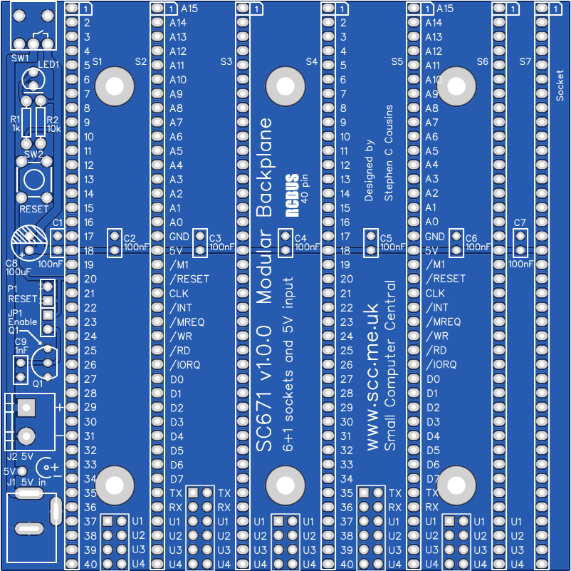
A typical SC600 series backplane is illustrated below.

Jumper options
| Jumper | Function |
| JP1 | Connect voltage supervisor, Q1, to the reset signal |
| JP 2, 4, 6 | JPx.1 Connect P37 signal between bus sockets JPx.2 Connect P38 signal between bus sockets* JPx.3 Connect P39 signal between bus sockets* JPx.4 Connect P40 signal between bus sockets * See daisy chain details below Thin tracks on the under side of the PCB link these jumper positions, thus signals P37, 38, 39 and 40 are connected to each backplane socket. |
| JP 3, 5 | JPx.1 Connect TX signal between bus sockets JPx.2 Connect RX signal between bus sockets JPx.3 Connect P37 signal between bus sockets JPx.4 Connect P38 signal between bus sockets* JPx.5 Connect P39 signal between bus sockets* JPx.6 Connect P40 signal between bus sockets * See daisy chain details below Thin tracks on the under side of the PCB link these jumper positions, thus signals P37, 38, 39 and 40 are connected to each backplane socket. |
JP2 to JP6 allow some signals to be isolated between bus sockets. This can be helpful if there are several modules that use these signals for different functions.
Thin tracks on the under side of the PCB link these jumper positions, thus signals P37, 38, 39 and 40 are connected to each backplane socket. To isolate any of these signals it is necessary to cut the required thin track. Most users will not need to do this. It is only more complex set ups that need any of these signals isolated.
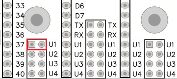
Typically the signals will be connected straight through to each bus socket by fitting jumper shunts horizontally, as illustrated to the left.
One such use is creating a Z80 mode 2 interrupt daisy chain

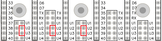
Alternatively, a daisy chain can be created from pin 39 to 38. This requires a jumper shunt to be fitted in the position illustrated to the left. A second daisy chain can be created from pin 43 to 42.
A daisy chain is created with two pins on each module. One pin is an output signal while the other is an input signal. The jumper connects the output of one module to the input of the next. The illustration below shows the jumper positions required to create a daisy chain between four modules, in bus sockets K1 to K4.
Daisy chains are typically use to create a priority ‘chain’. In the case illustrated above the output is from pin 39 of one module and this is connected to the input pin 38 on the input of module to the right. This creates a priority chain where the modules on the left are a higher priority than modules on the right.
Typical uses for a daisy chain are the Z80 mode 2 interrupt priority, IEI and IEO signals. This is specified as using pins 39 and 38. The second chain, using pins 43 and 42 can be used for a DMA priority chain.
Priority chains require all bus slots in the chain to be occupied by suitable modules. A gap can be left by fitting a pair of jumper shunts horizontally to pass the input and output signals straight through to the bus socket not use the chain signals, rather than being crossed from output to input pins.
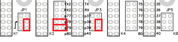
The illustration above configures the backplane for a daisy chain where bus socket K3 does not receive a crossed chain signal and thus should not contain a module which is part of the chain. Socket K3 can be empty or can contain a module which does not have connections to pins 39 or 38.
