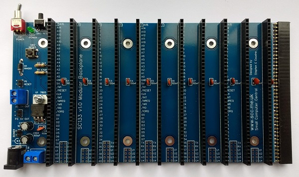
SC133 is a modular backplane with RC2014 compatible 40-pin bus sockets.
- SC133 – Description
- SC133 – Assembly guide
- SC133 – Forum (rc2014)
- SC133 – Forum (retro-comp)
- SC133 – Parts list
- SC133 – Printed circuit board
- SC133 – User guide
Downloads
- SC133 – Kit contents sheet (PDF)
- SC133 – Schematic v1.0 (PDF)
- SC133 – 3D printed mounting rails at thingiverse.com
Suppliers
| Kits | Website | From | Currency |
| Small Computers Direct | SCDirect | UK | GBP |
| Stephen C Cousins | Tindie | UK | USD |
| Small Computer Central | Lectronz | UK | Euro/USD |
| PCBs | Website | From | Currency |
| Small Computers Direct | SCDirect | UK | GBP |
| Stephen C Cousins | Tindie | UK | USD |
| Small Computer Central | Lectronz | UK | Euro/USD |
| Assembled and Tested | Website | From | Currency |
| Not available | |||
| Components | |||
| See parts list |
Tindie does not collect VAT for EU countries
Lectronz does collect EU VAT for orders up to 150 EUR
Description
SC133 is a modular backplane designed for the RC2014 bus.
The main features of this design are:
- 11 vertical RC2014 bus compatible sockets (40-pin)
- 1 horizontal RC2014 bus compatible socket (40-pin)
- Expandable with additional modular backplane sections
- Voltage regulator (5 volts, 1 amp) for 8 to 15-volt input
- On/Off toggle switch
- Power indicator LED
- Power input via 2.1mm power jack or screw terminals
- Front-facing reset button
- Top facing reset button
- 5-volt output via screw terminals and header pins
- User pins (U1 to U4) and serial pins (TX and RX) can be isolated by cutting thin tracks on the underside of the PCB.
User Guide
SC133 is a modular backplane designed for the RC2014 bus.
Power input
The backplane has been designed to be powered from a D.C. supply between 8 and 15 volts, and may draw up to 1 ampere.
Power can be connected via a 2.1 mm power jack (J1), or via screw terminals (J2), or via header pins (P2). The power jack must be wired for centre positive.
The input power can be switched on and off with the toggle switch (SW1). The switched supply is then fed to the 7805 regulator which reduces the input voltage to 5 volts. The power LED (LED1) indicates the presence of the 5 volt supply.
The regulated 5 volt power can be taken from the backplane via screw terminals (J3) or header pins (P3) to power external circuitry.
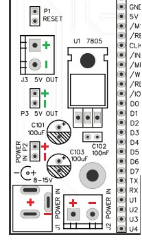
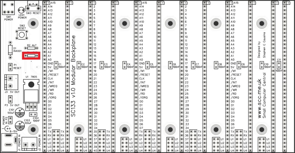
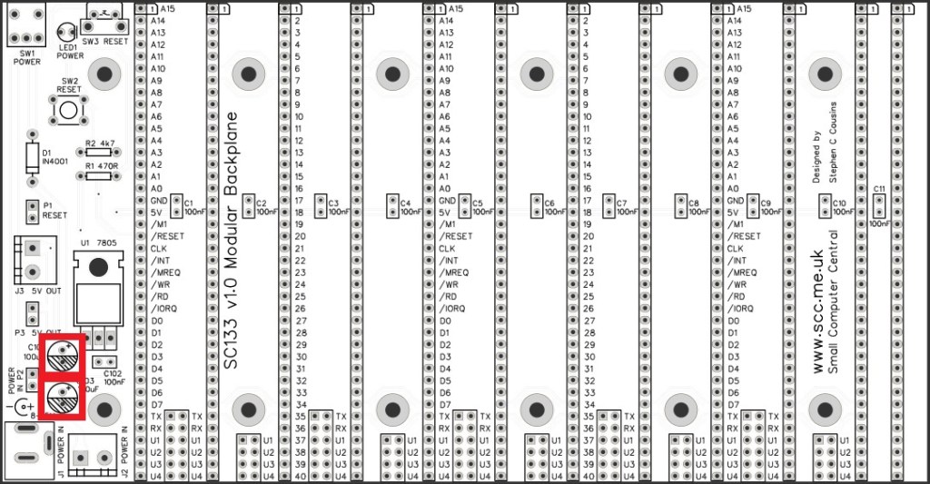
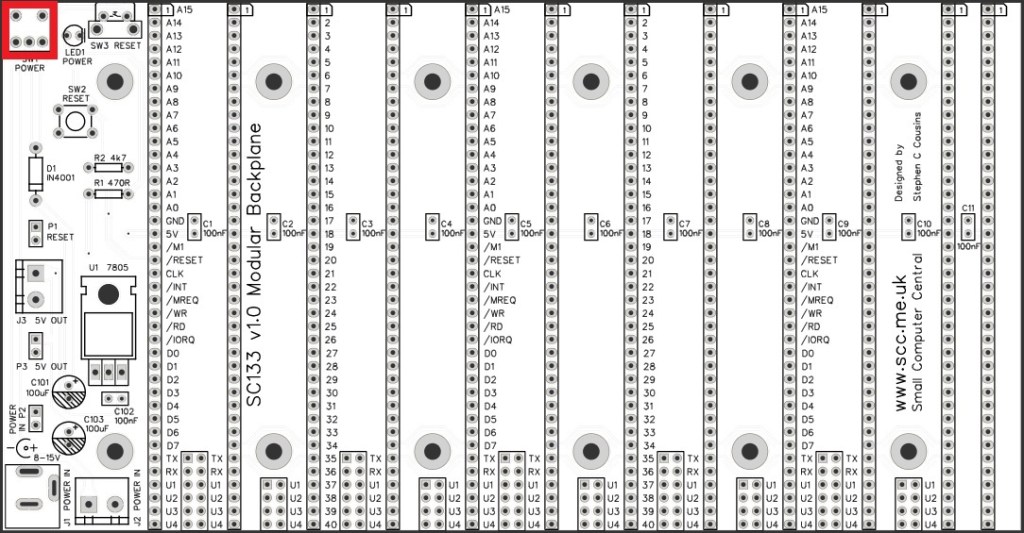
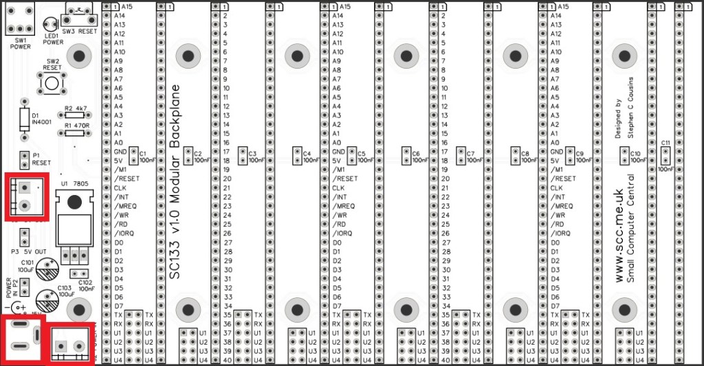
The illustration (right) shows the power connectors on the backplane.
The red “+” and “-” indicate points where an 8 to 15 volt supply can be connected to power the system.
The green “+” and “-” indicate points where a 5 volt output is available to power other devices. This is the voltage regulated by the 7805 (U1) and switched on and off by the toggle switch (SW1).
Reset
The backplane includes two reset buttons, one facing straight up and the other facing forwards. These buttons both pull the reset signal low. An external reset button can be connected via header pins (P1), if required. The reset signal can also be pulled low by switches or circuitry on any connected module.
Module sockets
The backplane has 11 vertical and 1 horizontal RC2014 bus compatible 40-pin module sockets. RC2014 bus compatible modules can be connected to any of these sockets.
It should be noted that modules designed for the enhanced RC2014 bus, which has a partial second row of pins, may not work with 40-pin bus sockets, or may work with limitations. Similarly, modules designed for extended RC2014 style bus systems, such as the 80-pin bus, may not work.
The horizontal bus socket allows a module to be connected horizontally which can make access easier during development or debugging. In addition this socket allows the backplane to be extended by connecting additional modular backplane sections, such as SC113.
Option links
It may be desirable to isolate some signals on the backplane. This might be necessary if you have, for example, two serial modules, each linked to its own terminal module. This set up would require the signals between the first serial module and its terminal module, to be isolated from the signals between the second pair of modules.
To isolate a signal from one or more module sockets, cut the thin track on the bottom of the board.
These are the isolation links as seen on the bottom of the printed circuit board:
| Short row | Long row |
| TX | |
| RX | |
| User 1 | User 1 |
| User 2 | User 2 |
| User 3 | User 3 |
| User 4 | User 4 |
Parts List
Printed Circuit Board

| Links |
| SC133, v1.0, PCB only (Tindie) |
| SC133, v1.0, Complete kit (Tindie) |
| SC133, v1.0, PCB design files (OSHWLab) |
| SC133, v1.0, Gerber files (ZIP) |
Assembly Guide
Experienced builders can just go ahead and populate the board. There shouldn’t be any surprises to catch you out.
This guide assumes you are familiar with assembling circuit boards, soldering, and cleaning. If not, it is recommended you read some of the guides on the internet before continuing.
First check you have all the required components.
Before assembling it is worth visually inspecting the circuit board for anything that looks out of place, such as mechanical damage or apparent manufacturing defects.
If you have a multimeter that measures resistance or has a continuity test function, check there is not a short on the power supply tracks. Connect the probes to each terminal of one of the capacitors, such as C1. This should be an open circuit, not a short.
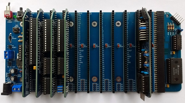
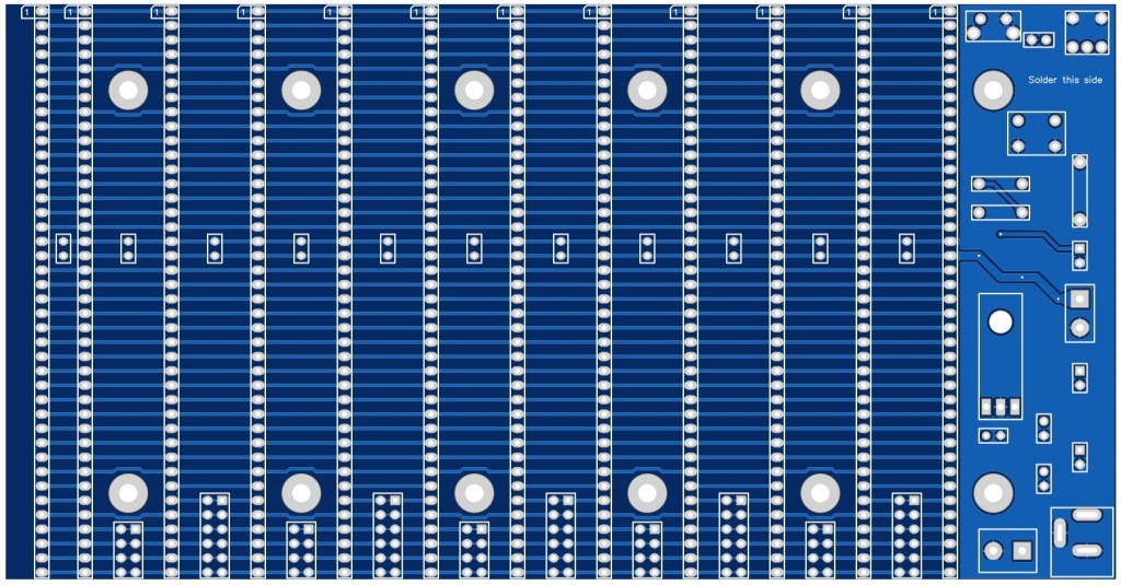
The picture below shows what a completed SC133, modular backplane should look like.
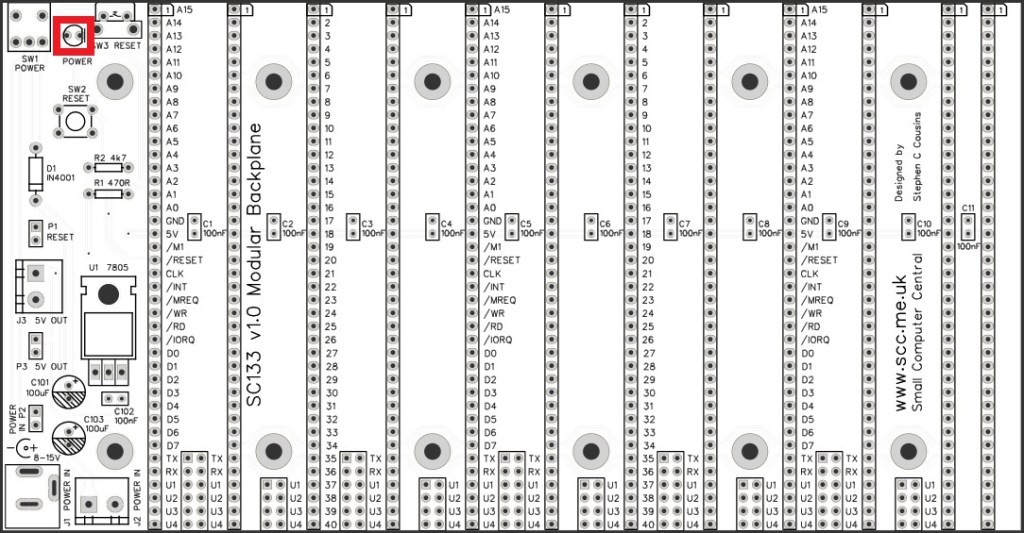
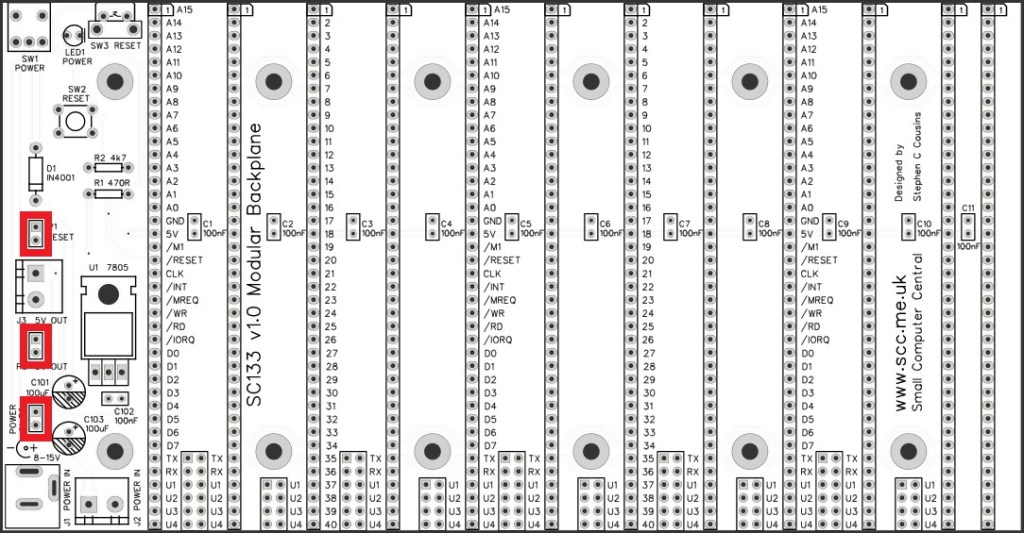
Resistor 470R
Fit and solder the 470R resistor R1 (shown below in red).
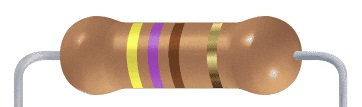
Resistors can be fitted either way around, as they are not polarity dependent.
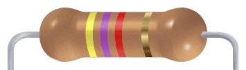
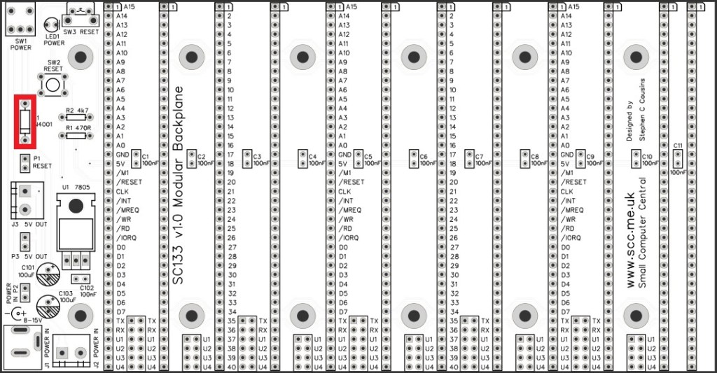
Resistors 4k7
Fit and solder the 4k7 resistor R2.
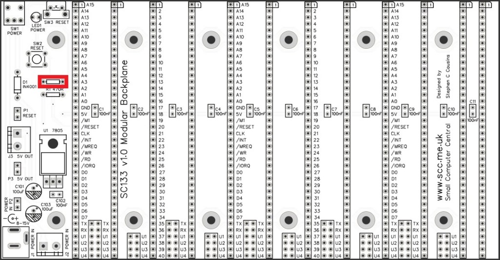
Diode 1N4001
Fit and solder the 1N4001 diode D1.
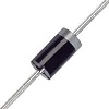
Diodes must be fitted the correct way around. The light coloured band at one end of the diode must be fitted into the circuit board at the end indicated by the silkscreen.
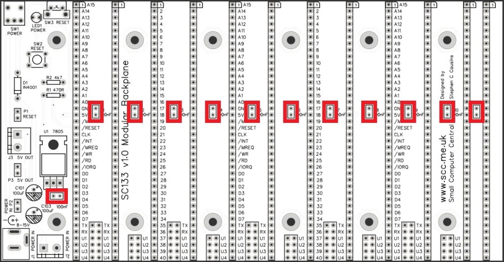
Capacitors 100 nF (0.1 µF)
Fit and solder capacitors C1 to C11, and C102.
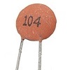
These capacitors can be fitted either way around, as they are not polarity dependent.
The exact value of this component is not critical. The use of very cheap capacitors within the range of about 30 to 200 nF is acceptable.
Capacitor 100 µF
Fit and solder capacitors C101 and C103.
It is important to fit this capacitor the right way around. The negative terminal is indicated with a ‘minus’ sign, as illustrated to the right. The negative terminal also has a shorter lead.
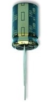
The silkscreen has a plus sign for the positive terminal and a hashed area for the negative terminal
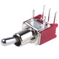
Toggle switch
Fit and solder the toggle switch SW1.
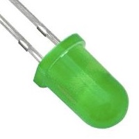
Light Emitting Diode (LED)
Fit and solder the LED (LED1).
It is important to fit the LED the correct way around. LEDs usually have a small flat side to indicate the cathode (the negative end). This should be positioned to match the flat side shown on the circuit board (illustrated to the right). Also, the cathode pin on the LED is usually shorter than the other pin (the Anode).

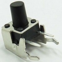
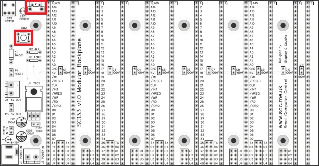
Reset switches
Fit and solder the two reset switches.
SW2 faces straight up.
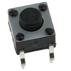
SW3 faces forward.
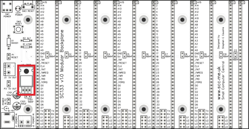
Voltage regulator 7805
Fit and solder the 7805 voltage regulator U1.

Bend the legs such that the hole in the heat sink part of the regulator lines up with the hole in the printed circuit board. Bolt the regulator in place with an M3.5 nut and bolt, then solder the pins.
Headers (straight, single row)
Fit and solder the pin headers P1, P2, and P3.
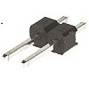
These header pins may need to be cut from longer strips using wire cutters to cut the plastic.
Bus socket (horizontal)
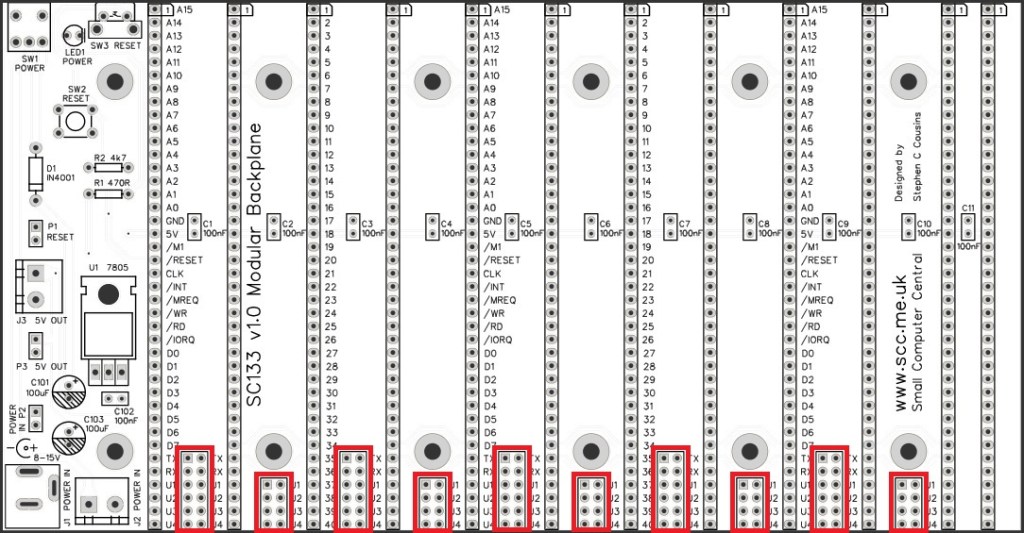
Fit and solder the right angled female header, 1 row x 40 pin, SK12.

Power connectors
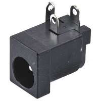
Fit and solder the 2.1 mm power jack socket, J1.
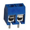
Fit and solder the two screw terminal blocks, J2 and J3.
Ensure the the wire entry holes face the edge of the PCB.
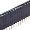
Bus sockets (vertical)
Fit and solder the straight female headers, 1 row x 40 pin, SK1 to SK11.
Quick Tests
Repeat the check made earlier for a short on the power supply tracks. Connect the meter probes to the terminals of J2. This should be an open circuit, not a short. If you are using a digital meter set to measure resistance it will likely take a few seconds for the reading to stabilise as there are now capacitors on the power lines. A reading of more than 100k Ω (100000 ohms) is acceptable. Repeat with the toggle switch, SW1, in the other position.
Optional
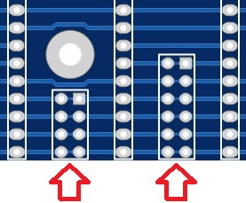
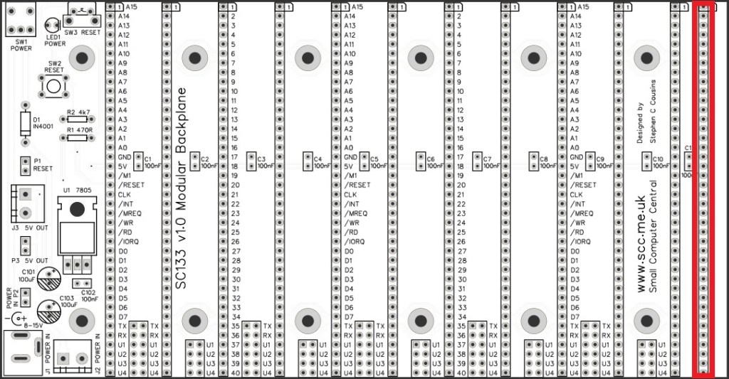
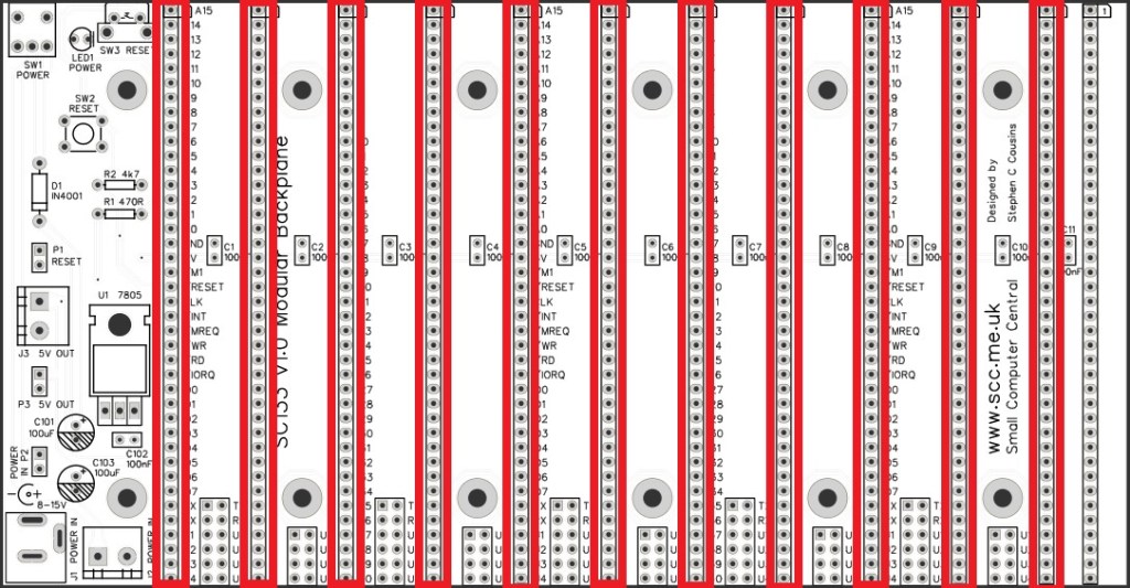
The backplane includes a set of isolation points between the module sockets, as shown below. These allow some signals to be isolated between modules.
The PCB is manufactured with thin tracks linking these isolation points such that these signals are connected to all the module sockets. If you wish to isolate some signals it is necessary to cut the appropriate thin track on the solder side of the PCB.
The table below shows the signals that can be isolated.
| Label | Signal name |
| TX | Serial transmit |
| RX | Serial receive |
| U1 | User #1 |
| U2 | User #2 |
| U3 | User #3 |
| U4 | User #4 |
Should you wish to reconnect the signals you can solder a link in the appropriate place. Alternatively, you can solder header pins and use jumper shunts to connect the required signals.
Inspection
Remove any solder ‘splats’ with a brush, such as an old toothbrush.
Visually inspect the soldering for dry joints and shorts.
Clean the flux off with suitable cleaning materials.
Visually inspect again.
Notes
- This design is made in accordance with the “designed for RC2014” labelling scheme.
- RC2014 is a trademark of RFC2795 Ltd.
- This product is designed for hobby use and is not suitable for industrial, commercial or safety-critical applications.
- The product contains small parts and is not suitable for young children.
