SC132 is a dual asynchronous serial module for the RC2014 bus.

Suppliers
| Kits | Website | From | Currency |
| Small Computers Direct | SCDirect | UK | GBP |
| Stephen C Cousins | Tindie | UK | USD |
| Small Computer Central | Lectronz | UK | Euro/USD |
| PCBs | Website | From | Currency |
| Small Computers Direct | SCDirect | UK | GBP |
| Stephen C Cousins | Tindie | UK | USD |
| Small Computer Central | Lectronz | UK | Euro/USD |
| Assembled and Tested | Website | From | Currency |
| Not available | |||
| Components | |||
| See parts list |
Tindie does not collect VAT for EU countries
Lectronz does collect EU VAT for orders up to 150 EUR
Examples
Description
SC132 is a module for the RC2014 bus. It houses a Z80 SIO/0 chip and provides two TTL serial ports for use with FTDI style serial adapter cables.
The main features of this module are:
- Compatible with existing software/firmware for SIO/2
- Full Z80 mode 2 interrupt support (IEI/IEO daisy-chain)
- Two TTL serial ports for use with FTDI serial adapter cables
- Support for two boards in a system at 0x80 and 0x84
- Source of bus clock (option) to potentially reduce board count
- On-board clock option to make it independent of the CPU clock
- Baud rate controllable in software when used with SC102 Z80 CTC
User Guide
SC132 is a two channel asynchronous serial interface module based on a Z80 SIO/0 and designed for the RC2014 bus.

This module is software compatible with modules based on the Z80 SIO/2, such as:
- Official RC2014 dual serial SIO/2 module
- SC104 Z80 SIO/2 module
It is therefore compatible with the following RC2014 firmware:
- Small Computer Monitor
- Official RC2014 firmware images 2, 4, 6, 88, 9
- RomWBW with SIO support enabled
For compatibility with the official RC2014 SIO module, the address should be set to 80 (hexadecimal) and the clock source should be 7.3728 MHz.
Quick Guide to Jumpers
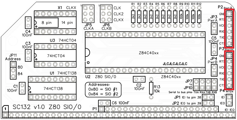
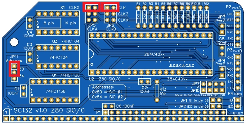
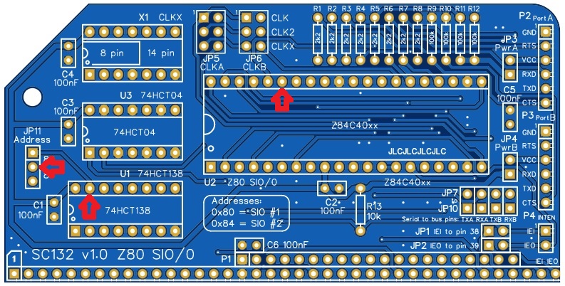
As a quick guide to getting started: Fit a jumper shunt in the position shown below.

JP11 sets the module’s I/O address to hexadecimal 80, which is the standard address for the primary serial module in a system.
JP5 and JP6 select the bus clock as the clock source for the Z80 SIO. Most software assumes the SIO has a 7.3728 MHz clock .
Serial Ports
The module has two asynchronous serial ports. These are 5 volt FTDI style ports.
The pin-out, below, describes signals with respect to SC132, so an output is a signal from the SC132 to a computer or terminal.
| Pin | Function |
| 1 | Ground (GND) |
| 2 | Request To Send (RTS) output |
| 3 | Vcc (5V) |
| 4 | Recieve Data (RxD) input |
| 5 | Transmit Data (TxD) output |
| 6 | Clear To Send (CTS) input |
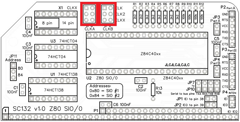
A typical FTDI style serial adapter is illustrated to the right.
This is fitted to the serial port by a 6-way Dupont cable.
The default serial port settings are as follows:
| Setting | Default |
| Baud rate | 115200 |
| Data bits | 8 |
| Parity | none |
| Stop bits | 1 |
| Flow control | Hardware (recommended) |
The default serial port connection is P2, Serial Port A.
Power
SC132 is typically connected to a computer or terminal with an FTDI style serial adapter. This adapter can, optionally, provide power for the whole retro system. Alternatively, this module can be powered from the backplane.
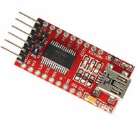
To enable power from serial port A (P2), fit a jumper shunt to JP3. To enable power from serial port B (P3), fit a jumper shunt to JP4.
WARNING: You should normally only connect one power source to the system at a time.
As power can flow either way, the jumpers, JP3 and JP4, also enable serial devices to be powered from this module.
Bus signal options
Jumpers JP1, JP2, JP7, JP8, JP9, and JP10 enable some signals to be optionally connected to the bus.
| Signal | Jumper | Bus pin |
| IEI | JP1 | 38 (USER 2) |
| IEO | JP2 | 39 (USER 3) |
| TxA | JP7 | 35 (TX) |
| RxA | JP8 | 36 (RX) |
| TxB | JP9 | 75 (TX2) |
| RxB | JP10 | 76 (RX2) |
Signals IEI and IEO support a Z80 mode 2 interrupt daisy chain. Jumper shunts should only be fitted to JP1 and JP2 if you have a backplane set up to use pins 38 and 39 as an interrupt daisy chain. A daisy chain is not required unless you have suitable hardware and software to support it.
Jumper shunts can usually be fitted to JP7 to JP10 as these bus signals are specifically for the serial signals Tx and Rx. The only reason to not fit them is if you have another device on the bus that would conflict, such as a second serial module.
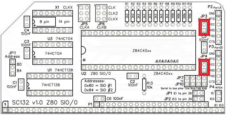
Clock sources
This modules allows each SIO channel to be clocked from either the main bus clock (typically 7.3728 MHz), the secondary bus clock, or the optional on-board oscillator (X1). Jumpers JP5 and JP6 provide these options.
Parts List
| Reference | Qty | Component |
| PCB | 1 | SC132, v1.0, PCB |
| C1 to C5 | 6 | Capacitor, ceramic, 100 nF |
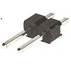
| JP1 plus JP2 | 1 | Header, male, 2 x 2 pin, straight |
| JP3 and JP4 | 2 | Header, male, 1 x 2 pin, straight |
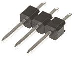
| JP5 and JP6 | 2 | Header, male, 2 x 3 pin, straight |
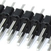
| JP7 plus JP8 plus JP9 plus JP10 | 1 | Header, male, 2 x 4 pin, straight |
| JP11 | 1 | Header, male, 1 x 3 pin, straight |
| JP1 to JP11 | 11 | Jumper shunt |
| P1 | 1 | Header, male, 2 x 39 pin, angled |
| P2 and P3 | 2 | Header, male, 1 x 6 pin, angled |
| P4 | 1 | Header, male, 1 x 2 pin, angled |
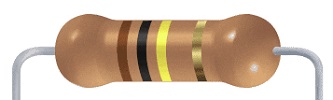
| R1 to R8 | 8 | Resistor, 2k2, 0.25W |
| R9 to R12 | 4 | Resistor, 100k, 0.25W |
| R13 | 1 | Resistor, 10k, 0.25W |
| U1 | 1 | 74HCT138 |
| U1 socket | 1 | 16-pin DIP socket |
| U2 | 1 | Z80 SIO/0, Z84C4008PEG or Z84C4010PEG |
| U2 socket | 1 | 40-pin DIP socket |
| U3 | 1 | 74HCT04 |
| U3 socket | 1 | 14-pin DIP socket |
| X1 | 1 | Oscillator, 7.3728MHz (optional, not included in kit) |
| X1 socket | 1 | 14-pin DIP socket (optional, not included in kit) |
Printed Circuit Board

| Supplier | Website | Ships from |
| Stephen C Cousins | Tindie | UK |
| pcb4diy | eBay | Germany |
| pcb4diy | pcb4diy.de | Germany |
Assembly Guide
Experienced builders just go ahead and populate the board. There shouldn’t be any further surprises to catch you out.
This guide assumes you are familiar with assembling circuit boards, soldering, and cleaning. If not, it is recommended you read some of the guides on the internet before continuing.
First check you have all the required components.
Before assembling it is worth visually inspecting the circuit board for anything that looks out of place, such as mechanical damage or apparent manufacturing defects.
If you have a multimeter that measures resistance or has a continuity test function, check there is not a short on the power supply tracks. Connect the probes to each terminal of one of the capacitors, such as C1. This should be an open circuit, not a short.
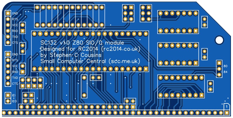
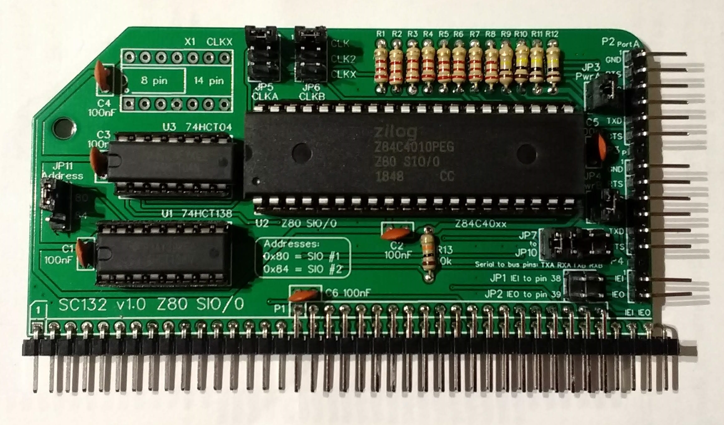
The picture below shows what a completed SC132, Z80 SIO/0 module should look like.
Resistors 2k2
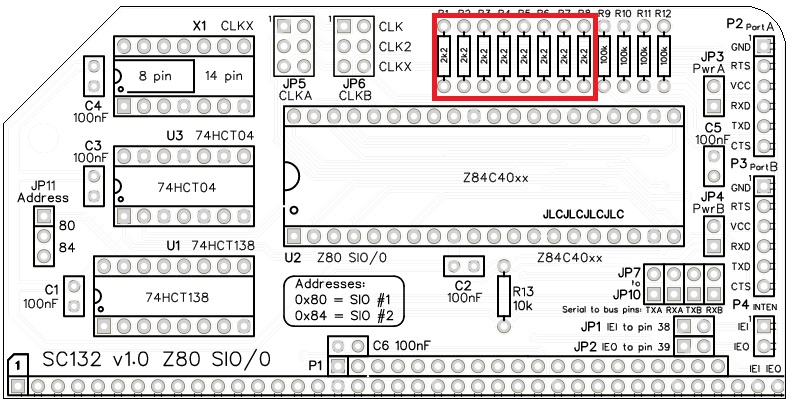
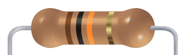
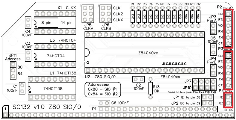
Fit and solder the 2k2 resistors R1 to R8 (shown below in red).

These can be fitted either way around, as they are not polarity dependent.
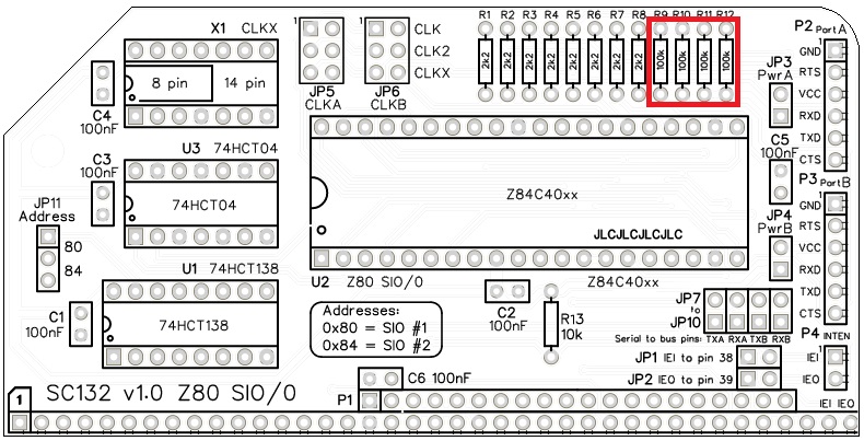
Resistors 100k
Fit and solder the 100k resistors R9 to R12.
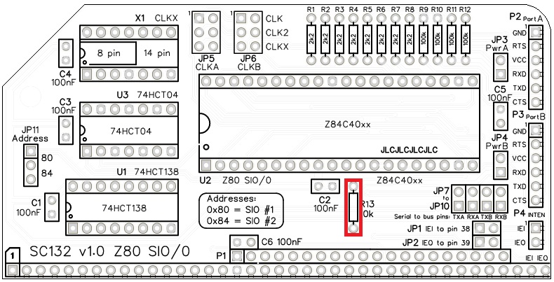
Resistors 10k
Fit and solder the 10k resistor R13.
IC sockets
Fit and solder the IC sockets.
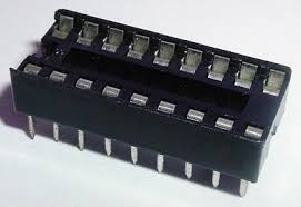
Be sure to fit them with the notch matching the legend on the circuit board, so you do not end up fitting the IC the wrong way around too.

Headers (angled, single row)
Fit and solder header pins P2, P3, and P4.
This can be either a single strip of 16 pins with two pins removed, as illustrated the photo at the start of this page, or as three separate strips.
Header (angled, double row)
Fit and solder header pins P1.
Some pins need to be removed to match the holes in the PCB.

Quick Test
It is now worth repeating the check made earlier for a short on the power supply tracks. Connect the meter probes to each terminal of one of the capacitors, such as C1. This should be an open circuit, not a short.
Capacitors 100 nF
Fit and solder capacitors C1 to C6.
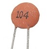
These capacitors can be fitted either way around, as they are not polarity dependent.
The exact value of this component is not critical. The use of very cheap capacitors within the range of about 50 to 100 nF is acceptable.

Quick Test
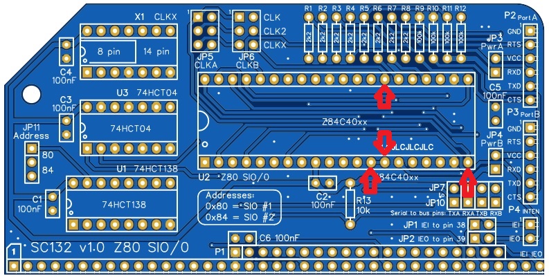
Again, repeat the check made earlier for a short on the power supply tracks. Connect the meter probes to IC U1 pin 16 (shown below in red) and U1 pin 8 (shown in green). This should be an open circuit, not a short. If you are using a digital meter set to measure resistance it will likely take a few seconds for the reading to stabilise as there are now capacitors on the power lines. A reading of more than 100 kΩ (100000 ohms) is acceptable.

Headers (straight, single row)
Fit and solder the pin header JP11, 1 row of 3 pins.
Fit and solder the pin headers JP3 and JP4, 1 row of 2 pins each.
These header pins may need to be cut from longer strips using wire cutters to cut the plastic.

Headers (straight, double row)
Fit and solder the pin header JP5 and JP6, 2 rows of 3 pins each.
Fit and solder the pin header JP7 plus JP8 plus JP9 plus JP10, a single 2 row of 4 pin header.
Fit and solder the pin header JP1 plus JP2, a single 2 row of 2 pin header.
These header pins may need to be cut from longer strips using wire cutters to cut the plastic.

Quick Tests
Repeat the check made earlier for a short on the power supply tracks. Connect the meter probes to IC U1 pin 16 (shown below in red) and U1 pin 8 (shown in green). This should be an open circuit, not a short. If you are using a digital meter set to measure resistance it will likely take a few seconds for the reading to stabilise as there are now capacitors on the power lines. A reading of more than 100k Ω (100000 ohms) is acceptable.

Measure the resistance between U1 pin 16 (red) and U2 pin 6 (blue). This should be 10k ohms. Anything from 9k to 11k is acceptable.
Measure the resistance between U1 pin 16 (red) and the RxD pin of P2 and P3 (brown). These should be 100k ohms. Anything from 90k to 110k is acceptable.
Measure the resistance between U1 pin 8 (green) and the CTS pin of P2 and P3 (orange). These should be 100k ohms. Anything from 90k to 110k is acceptable.
Inspection
Remove any solder ‘splats’ with a brush, such as an old toothbrush.
Visually inspect the soldering for dry joints and shorts.
Clean the flux off with suitable cleaning materials.
Visually inspect again.
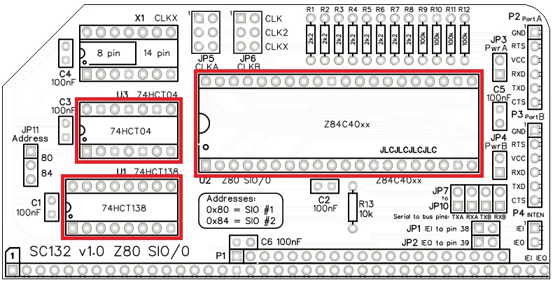
Integrated Circuits
If all the above tests check out okay, insert the integrated circuits into their sockets.
Initial Testing
Fit a jumper shunts in the positions shown below.
Insert the module into an RC2014 compatible backplane. The backplane should also include a CPU, ROM, RAM, clock, and reset. The ROM should contain firmware that supports a Z80 SIO serial port. This test assumes the system has a 7.3728 MHz main clock.
Connect an FTDI style serial cable to Port A (P2) and connect the other end to a computer running terminal emulations software. The terminal should be set to 115200 baud, 8 data bits, 1 stop bit, no parity, no flow control (at least for this initial test).
Power up and hopefully your terminal will display an appropriate start up message.
Troubleshooting
The default SIO address is 0x80. This is the address assumed for the first Z80 SIO by existing firmware and software. SC132 provides for an alternative address at 0x84, but this requires appropriate software support.
Jumper shunts should be fitted in the positions shown below. If powering the system from the serial port, fit a shunt at JP3.
With a digital meter, check the supply voltage reaching the module is between 4.75 and 5.25 volts. Ideally check this voltage on the power supply pins on each IC.
The Small Computer Monitor (SCM) should automatically identify SC132 if it is connected either the RC2014 standard bus, the RC2014 enhanced bus, or an extended RC2014 bus, such as BP80, provided the module is set to address 0x80.
Activity on TXD
If you have a logic probe or oscilloscope you should see a very brief burst of activity on the TXD line at connector P2 just after the reset button is released. This is the SCM start up messaging being transmitted. You are unlikely to be able to detect this with a volt meter.
If this activity is seen then things are looking very good as the SIO has been identified, configured, and data is being transmitted. If not, then continue with the tests below.
Clock signals
The SIO requires four clock signals on the pins illustrated below. These can be all the same signal or they can be independent. The main bus clock should be present on U2 pin 20. The serial data clocks should be present on U2 pins 13, 14, and 27.
The clock signals can be checked with a digital meter by measuring the voltages on these pins. The voltage should be between 2 and 3 volts.
Address decoding
With a digital meter, measure the voltage at U1 pin 15, U2 pin 25, and the address jumper (illustrated below). This should be at least 4 volts.
This signal is the chip select signal, which should also reach the SIO pin 35. If this signal is not correct the SIO will not be selected and will thus not work.
If you have an oscilloscope or logic probe you should see the pin is either:
- regularly pulsing low but slower than once every 5 microseconds, indicating the SIO has been recognised.
- steady logic high, indicating the SIO has not been recognised.
Use SCM to enter the following test program.
8000:  DB 80    IN A,(80)
8002:  18 FC    JR 8000
Run the program with the command “G 8000” and measure the voltage at U1 pin 15 again. The voltage should now be at least 0.5 volts lower than the first measurement.
If you have an oscilloscope or logic probe you should see the pin is pulsing low once every couple of microseconds.
If this signal is not correct the address decoding would appear to be faulty. Address decoding is handled by U1 (74HCT138).
A further test you can perform to check the address decoding and also the response from the SIO, is the read from the input port addresses associated with the SIO. Use the SCM input command “I” (that’s’I’ not ‘L’) to read an input port. Read each address from 80 to 87. For example: “I 80”. The SIO should be seen from 80 to 83, while there should not usually be a device from 84 to 87. Typically, 84 to 87 will read 78 but that is not guaranteed. Address 80 to 83 will be the SIO registers. There should be an obvious difference in the values from these two ranges. If 80 to 83 looks the same as 84 to 87 then the SIO is either not begin selected or is not working.
Notes
- This design is made in accordance with the “designed for RC2014” labelling scheme.
- RC2014 is a trademark of RFC2795 Ltd.
- This product is designed for hobby use and is not suitable for industrial, commercial or safety-critical applications.
- The product contains small parts and is not suitable for young children.
