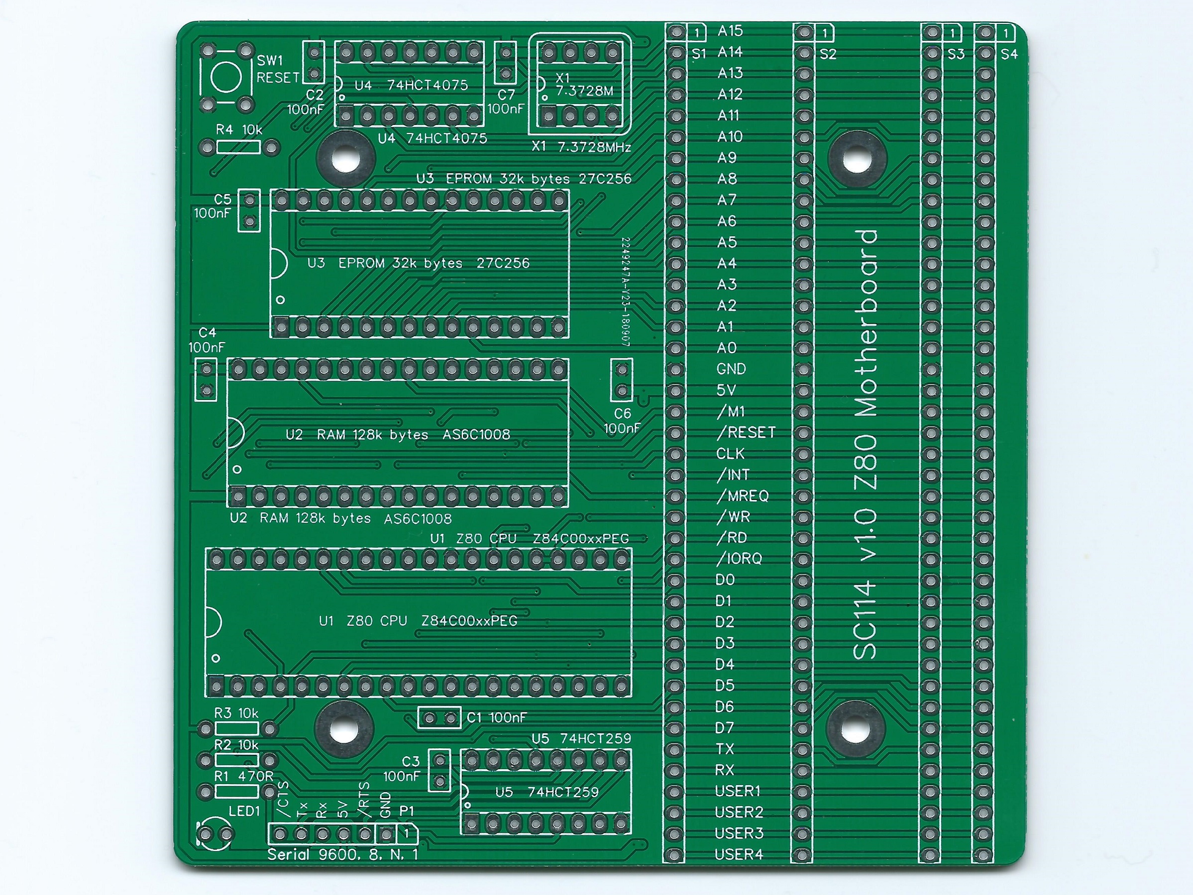
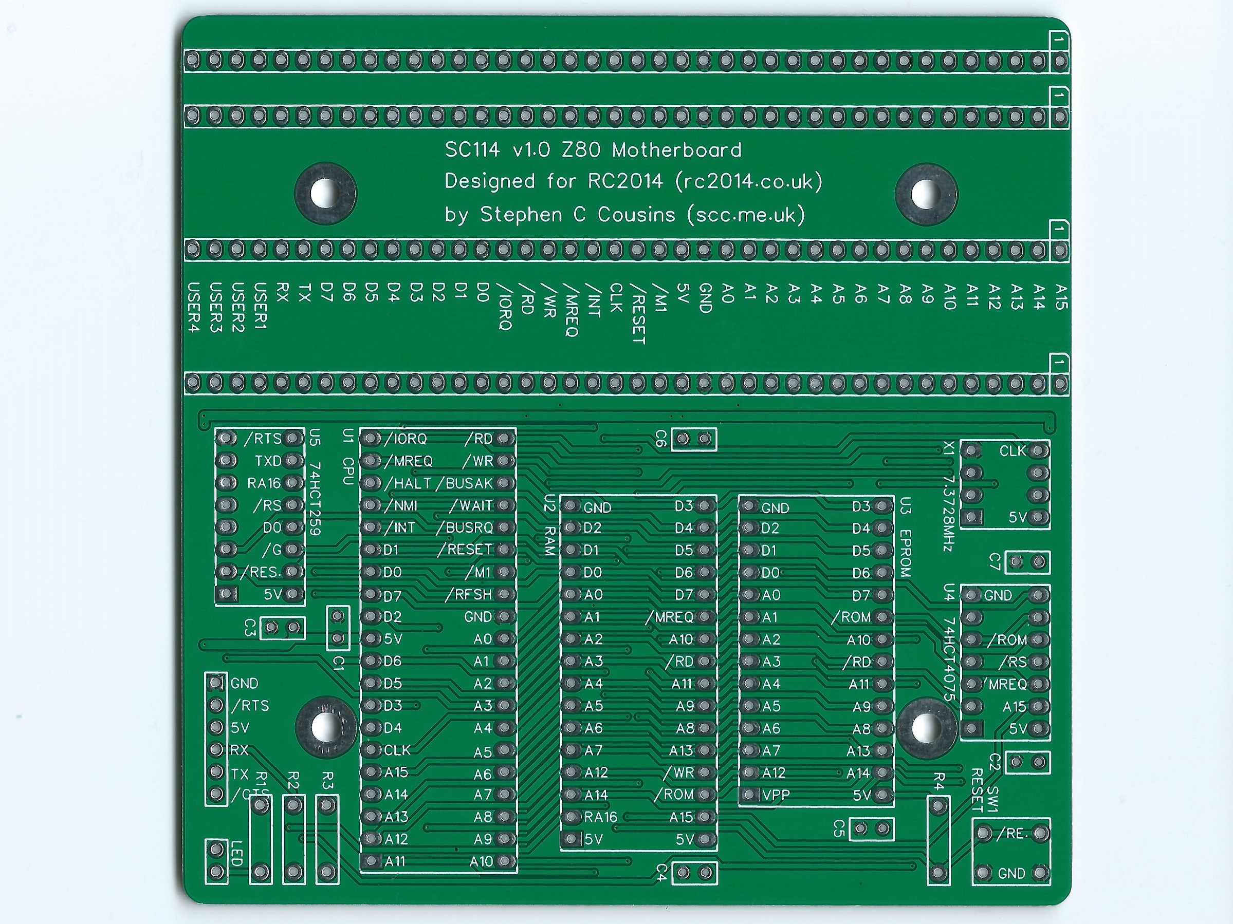
SC114 is a Z80 single board computer, in a motherboard format, with RC2014 compatible expansion slots. It is easy to build and low cost, making it a great introduction to the world of RC2014 compatible retro computers.

Documentation
- SC114 – Assembly Guide
- SC114 – Circuit Explained
- SC114 – Compatibility
- SC114 – Firmware, SCM S2
- SC114 – Photo Gallery
- SC114 – Parts list
- SC114 – Printed circuit board
- SC114 – Software, CP/M 2.2
- SC114 – Software, SCM Apps
- SC114 – Support
Downloads
- SC114 – Firmware, SCM S2
- SC114 – Kit contents sheet (PDF)
- SC114 – Schematic v1.0.1 (PDF)
- SC114 – 3D printed parts at thingiverse.com
- SC114 – 3D printed mounting rails at thingiverse.com
Suppliers
| Kits | Website | From | Currency |
| Small Computers Direct | SCDirect | UK | GBP |
| Stephen C Cousins | Tindie | UK | USD |
| Small Computer Central | Lectronz | UK | Euro/USD |
| PCBs | Website | From | Currency |
| Small Computers Direct | SCDirect | UK | GBP |
| Stephen C Cousins | Tindie | UK | USD |
| Small Computer Central | Lectronz | UK | Euro/USD |
| Assembled and Tested | Website | From | Currency |
| Not available | |||
| Components | |||
| See parts list |
Tindie does not collect VAT for EU countries
Lectronz does collect EU VAT for orders up to 150 EUR
Examples
Older Versions
Description
The aim of this design is to make entry into the RC2014 universe easier and more reliable, by using fewer components, less soldering, fewer configuration jumpers, and fewer circuit boards.
This motherboard can work in a modest way as a single board computer (SBC), yet can easily be expanded to run CP/M and more.
Here are the specs:
- Z80 running at 7.3728 MHz
- 128k bytes RAM (second 64k not easy to use, so best consider it to be 64k usable)
- 32k bytes ROM, which can be paged out with the usual write to port 0x38
- Simple bit-bang serial port to get you started
- Four RC2014 standard bus sockets
- Simple reset button (no power on reset or reset debounce)
- LED for power and status indication
- Runs the Small Computer Monitor, with ROM BASIC and the CP/M loader included
- Printed circuit board size 102 mm x 102 mm
- Comprehensive documentation
The idea is that you can build the board without even fitting those tedious RC2014 sockets, then test it with the simple bit-bang serial port. This only involves assembling the components shown above. That’s 5 chips + oscillator + 6 pin header + a few Rs and Cs + LED + reset button.
Looks like this takes about 175 solder joints. Sounds a lot, but way fewer than typical RC2014. Should be a good chance of such a simple circuit working the first time. If it doesn’t work then it is a relatively simple circuit to troubleshoot. The onboard LED can flash results of the self-test so a serial port problem will not look like a dead processor.
You can then add the four 40 pin RC2014 module sockets. So that’s a further 160 solder joints, but it is incremental assembly thus relatively easy to work out where any new fault is.
The next step would be to build and test a proper serial port, such as the official Z80 SIO module. Then if you want CP/M all you need to add a Compact Flash module and a Compact Flash card with the standard CP/M distribution installed. All this is supported by the ROM with no configuration required.

You can even add backplanes from the modular backplane range, although their functionality is limited by the single row standard 40 pin expansion socket on the motherboard.
The motherboard has relatively few components and is thus quite a cheap build, so if it does not prove expandable enough it is not a big deal to discard it, take the useful modules, and move to a more advanced system.
Suitable expansion options are described here.
User Guide
The Z80 Motherboard is designed to be low cost and easy to assemble, with the ultimate aim of making it a more reliable build.
It has few components and thus less soldering, and can even be assembled without the expansion sockets to further reduce the amount of soldering. Jumper options have been avoided to reduce complexity and confusion.
The motherboard contains the following:
- Z80 running at 7.3728 MHz
- 128k bytes of RAM (second 64k not easy to use, so best consider it to be 64k usable)
- 32k bytes of ROM, which can be paged out with the usual write to port 0x38
- Simple bit-bang serial port to get you started
- Four RC2014 standard bus sockets
- Simple reset button (no power on reset or reset debounce)
- LED for power and status indication
- Runs the Small Computer Monitor configuration S2, with ROM BASIC and the CP/M loader included
User Guide, Getting started
Below is a very brief guide to getting started with the Z80 motherboard (SC114).
It is assumed the Z80 motherboard is fully assembled, but with no modules fitted in the RC2014 bus sockets. The ROM should contain the Small Computer Monitor v1.0 configuration S2 (available from http://www.scc.me.uk).
Connect a suitable FTDI style TTL level serial to USB adapter from P1 to a powered USB socket on a PC (or similar). The table below describes the typical connections from a USB adapter to the Z80 motherboard.
| USB Adapter | Direction | Motherboard |
| 1 = GND | < – > | 1 = GND |
| 2 = /CTS in | <<<<< | 2 = /RTS out |
| 3 = Vcc (5V) | < – > | 3 = Vcc (5V) |
| 4 = TXD out | >>>>> | 4 = RXD in |
| 5 = RXD in | <<<<< | 5 = TXD out |
| 6 = /DTR or /RTS out | >>>>> | 6 = /CTC in |
Press the reset button and check the LED lights. It should flash off and on again either once or twice.
- One flash off and on indicates a serial module has been detected on the RC2014 bus and is being used to connect to a terminal. Serial modules usually work at 115200 baud, 8 data bits, 1 stop bit, no parity and hardware flow control (RTS/CTS).
- Two flashes off and on indicate a serial module has not been detected and the onboard serial port (P1) is being used to connect to a terminal. This port works at 9600 baud, 8 data bits, 1 stop bit, no parity and hardware flow control (RTS/CTS).
- If the LED continues to flash the self-test has failed, most likely indicating the RAM is not working.
Start a suitable terminal emulation program, such as Tera Term, on the PC. Configure the PC’s serial port as indicated above.
Press the reset button on the Z80 motherboard. You should see the terminal program display something like “Small Computer Monitor – SC114”.
You are now ready to play!
This would be a good time to read the Small Computer Monitor tutorial and user guide.
User Guide, Port Addresses
The motherboard includes some simple input and output functions.
Output
The following are the output port addresses and their functions.
| Hexadecimal | Decimal | Function |
| 0x08 | 8 | Status LED (low = on) |
| 0x20 | 32 | Serial port, request to sent (RTS) |
| 0x28 | 40 | Serial port, transmit data (TXD) |
| 0x30 | 48 | RAM bottom 64k selected (active low) |
| 0x38 | 56 | ROM selected (active low) |
In each of the above cases, bit zero of the data byte determines the state of the output. If the onboard serial port is not in use, the serial port outputs can be used as simple digital output lines. These may be used for such purposes as turning LEDs on or off.
Input
A single input port is provided to read the serial data.
| Hexadecimal | Decimal | Function |
| 0x28 | 40 | Serial port, receive data (RXD) |
Bit 7 of the input port is the serial receive signal. This is a very crude input port and it is not recommended it be used for anything other than the serial receive input.
Decoding
The output port addresses are not tightly decoded. The full ranges of the output port addresses, expressed in binary and hexadecimal, are listed below.
| Bits: 7654 3210 | Hexadecimal | Function |
| 0000 10XX | 0x08 to 0x0B | Status LED (low = on) |
| 0010 00XX | 0x20 to 0x23 | Serial port, request to send (RTS) |
| 0010 10XX | 0x28 to 0x2B | Serial port, transmit data (TXD) |
| 0011 00XX | 0x30 to 0x33 | RAM bottom 64k selected (active low) |
| 0011 10XX | 0x38 to 0x3B | ROM selected (active low) |
If the onboard serial port is not being used for serial output or simple digital output, the addresses 0x20 to 0x23 and 0x28 to 0x2B can be used by other devices on the RC2014 bus.
User Guide, Software in ROM
In order for a computer to do anything useful, it needs some program code to execute. Even reading a program from a disk drive requires program code to perform that read. Thus a computer needs some program code permanently available to execute when it is first switched on. This is the function of the ROM chip.
The SC114 motherboard has been designed to have the Small Computer Monitor installed in the ROM chip, although any compatible code can be used instead. Currently, the recommended version of the Small Computer Monitor for this board is v1.0 configuration S2. This is available as both source code and HEX file from www.scc.me.uk as part of the Small Computer Workshop download. The hex file is in the folder: SCWorkshop\SCMonitor\Builds
This ROM contains a capable machine code monitor, a version of BASIC and a CP/M loader.
Monitor
The Monitor program provides a means of writing, entering, running and debugging machine code programs.
Documentation for the Monitor includes a tutorial, an installation guide, a user guide, and a reference sheet.
BASIC
The version of BASIC included in the ROM is the one supplied with most RC2014 systems. Documentation can be found online with support available on the RC2014-Z80 google group.
CP/M
The ROM contains a CP/M loader, but not CP/M itself.
To run CP/M you need a Compact Flash module, such as the official RC2014 Compact Flash module, and a prepared Compact Flash card (with CP/M installed on it).
The version of CP/M should be one of the versions produced for the RC2014. As CP/M includes its own device drivers, it is necessary to pick a version that matches the hardware you have.
Parts List
| Reference | Qty | Component |
| PCB | 1 | SC114, v1.0, PCB |
| C1 to C7 | 7 | Capacitor, ceramic, 100 nF |
| S1 to S3 | 3 | Header, female, 1 x 40 pin, straight |
| S4 | 1 | Header, female, 1 x 40 pin, angled |
| P1 | 1 | Header, male, 6-pin, straight |
| R1 | 1 | Resistor, 470R, 0.25W |
| R2 to R4 | 3 | Resistor 10k 0.25W |
| SW1 | 1 | Tactile button |
| LED1 | 1 | LED green 3mm |
| U1 | 1 | Z80 CPU Z84C0008PEG |
| U1 socket | 1 | 40-pin DIP socket |
| U2 | 1 | RAM 128k bytes AS6C1008 |
| U2 socket | 1 | 32-pin DIP socket |
| U3 | 1 | EPROM OTP 32k bytes 27C256 |
| U3 socket | 1 | 28-pin DIP socket |
| U4 | 1 | 74HCT4075 |
| U4 socket | 1 | 14-pin DIP socket |
| U5 | 1 | 74HCT259 |
| U5 socket | 1 | 16-pin DIP socket |
| X1 | 1 | Oscillator 7.3728 MHz |
| X1 socket | 1 | 8-pin PDIP socket (optional) |
Printed Circuit Board
| Supplier | Website | Ships from |
| Stephen C Cousins | Tindie | UK |
| pcb4diy | eBay | Germany |
| pcb4diy | pcb4diy.de | Germany |
Notes
- This design is made in accordance with the “designed for RC2014” labelling scheme.
- RC2014 is a trademark of RFC2795 Ltd.
- This product is designed for hobby use and is not suitable for industrial, commercial or safety-critical applications.
- The product contains small parts and is not suitable for young children.
