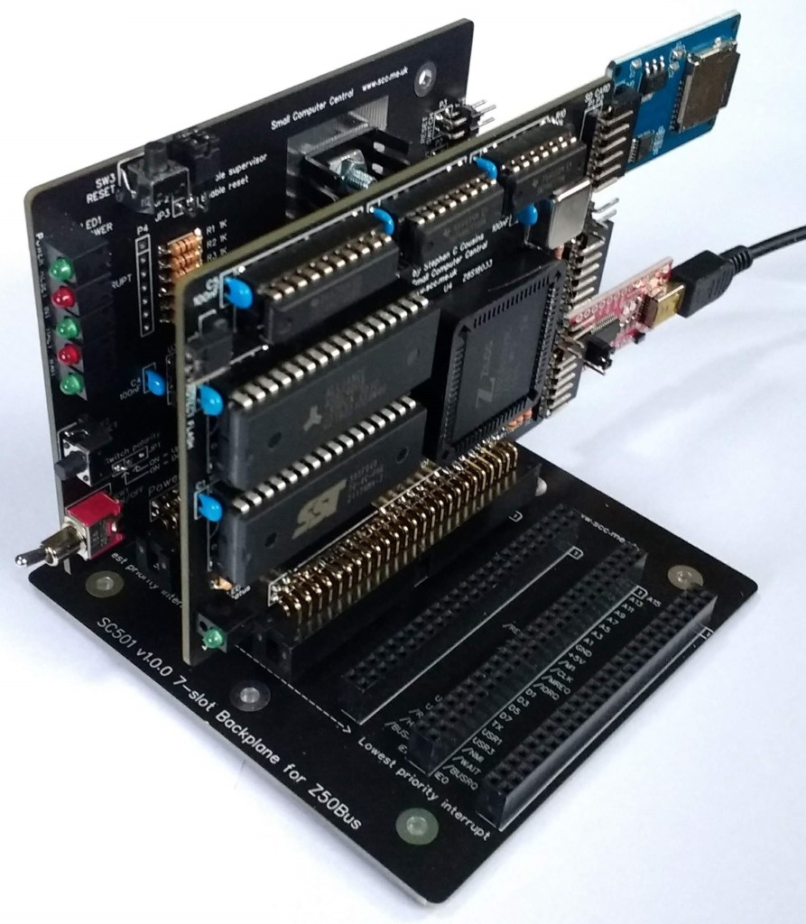
The SC500 is a modular 8-bit computer built around the Z50Bus. The system conforms to the Z50Bus specification with cards being the recommended “standard” size (100mm x 75mm).
- SC500 Series – Jumper Settings
- SC500 Series – Modifying Box Headers
- SC500 Series – Designing Your Z50Bus Computer
- SC500 Series – Hardware Compatibility
The design is open source with full details of the schematics, printed circuit board Gerber files, and software, either on this website or linked from this site. Kits are available for those who would like the convenience and reassurance that kits offer.
Software and firmware support includes RomWBW and CP/M.
The following modules are available.
- SC501 – Backplane, 7-slot, narrow spacing
- SC502 – Power supply and reset card, 8 to 15-volt input
- SC503 – Z180 processor card with serial and SPI (SD card)
- SC504 – Compact flash storage card
- SC505 – Real-time clock and I2C bus master
- SC506 – Digital I/O card
- SC507 – Backplane, 3-slot, narrow spacing
- SC508 – Backplane, 10-slot, wide spacing
- SC509 – Z80 PIO (Parallel I/O) card
- SC510 – Prototyping card
- SC511 – Serial (SIO) and timer (CTC) card
- SC512 – Prototyping breakout card
- SC513 – Modular backplane, 6-slot with 5-volt in and reset
- SC514 – Z80 CTC (Counter/Timer) card
- SC515 – Backplane, 14-slot, narrow spacing
- SC516 – Z80 processor card (CPU. memory, clock)
- SC517 – Modular backplane, RC2014 to Z50Bus
- SC518 – Z80 central processor unit (CPU) card
- SC519 – Z80 memory (128k+128k) card
- SC520 – Serial ACIA (68B50) card
- SC521 – Z80 SIO/2 (Serial I/O) card
- SC522 – Modular backplane, 6-slot, narrow spacing
- SC523 – Programmable ‘ROM’ card
- SC526 – Power supply and reset card, 5-volt input
Example Systems
The following are examples of systems that can be made with SC500 backplanes and cards.
- SC591 – Z180 computer running RomWBW and CP/M with storage
- SC592 – Z80 Pro computer running SCM and CP/M with storage
- Z80 computer running SCM and BASIC but with no storage
- Z80 computer running SCM and CP/M with storage
Popular additions to any of the above systems:
- SC506 – Digital I/O card
- Provides diagnostic ‘display’ (LEDs) at startup that can also be used as a simple software debugging ‘display’
- Includes 8 digital inputs and 8 digital outputs for interfacing to external electronics
- SC510 – Prototyping card
- Allows custom made additions to an SC500 series system
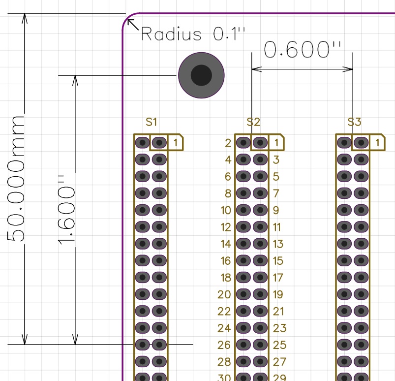
Card and Backplane Dimensions
The illustrations below show the dimensions of SC500 series cards and backplanes. The components are mostly arranged on a 0.1″ grid. The board dimensions are specified in millimetres to match the recommendations for a “standard” size Z50Bus card.
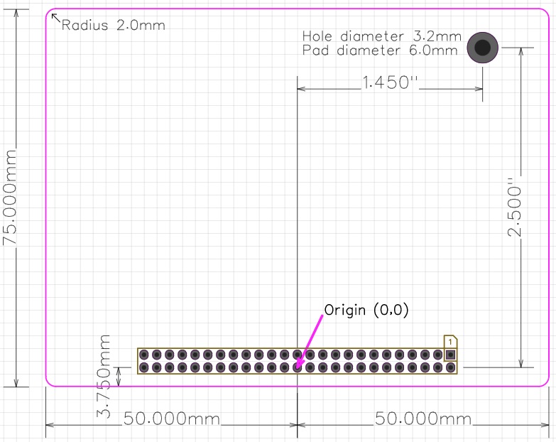
Socket spacing is either 0.6″ (narrow spacing) or 0.8″ (wide spacing).
I/O Device Addresses
The table below is LiNC’s suggested use of the limited I/O address space:
| I/O Address | Use |
| 0x00 to 0x3F | Processor card, SBC, or motherboard, and cards operating specifically with these devices |
| 0x40 to 0x4F | Available to third party vendors |
| 0x50 to 0x5F | Available to third party designs/vendors Alternative addresses for some LiNC cards |
| 0x60 to 0x7F | Specialist cards where address clashes are not likely |
| 0x80 to 0xAF | Core cards with well-specified functions Vendors are encouraged to map compatible cards here |
| 0xB0 to 0xDF | Available to third party vendors |
| 0xE0 to 0xFF | User’s own designs (suggested addresses) Do not use for products that are to be sold |
The recommendation for I/O device addresses for SCxxx products to best fit with LiNC’s suggestions is detailed in the tables below. The jumper positions for these defaults are illustrated here.
However, the actual addresses to be used will depend on the software being run, so consult software documentation for requirements.
The new range of Z50Bus compatible designs has part numbers starting “SC5”. Older designs have part numbers starting “SC1”.
Recommended input/output address map for SCxxx series systems:
| I/O Address | Use | Z50Bus Cards |
| 0x00 to 0x3F | Processor cards (Z80) | SC516 SC118 |
| 0x00 to 0x3F | Processor cards (Z180) | SC503 SC140 |
| 0x00 to 0x3F | Single Board Computers and Motherboards | – |
| 0x00 to 0x3F | Cards operating specifically with the above devices | SC519 SC523 |
| 0x40 to 0x5F | Not currently used | – |
| 0x60 to 0x63 | Z80 CTC (when not used as a system timer or baud generator) | SC514 |
| 0x64 to 0x7F | Not currently used | – |
| 0x80 to 0x83 | Z80 SIO #1 | SC511 SC521 SC125 |
| 0x84 to 0x87 | Z80 SIO #2 | SC511 SC521 SC125 |
| 0x88 to 0x8B | Z80 CTC #1 CTC 0 baud for SIO #1 port A CTC 1 baud for SIO #1 port B CTC 2/3 system timer | SC511 SC125 |
| 0x8C to 0x8F | Z80 CTC #2 CTC 0 baud for SIO #2 port A CTC 1 baud for SIO #2 port B CTC 2/3 user timer | SC511 SC125 |
| 0x90 to 97 or 0x10 to 17 * | 8-bit IDE direct on CPU bus Compact Flash controller #1 | SC504 SC127 |
| 0x98 to 0x9B | Z80 PIO #1 | SC509 |
| 0x9C to 0x9F | Z80 PIO #2 | SC509 |
| 0xA0 or 0x0D * | Digital I/O #1 | SC506 |
| 0xA1 or Ox0C * | RTC and I2C master | SC505 SC144 |
| 0xA2 to 0xA3 | Serial ACIA (68B50) #1 | SC520 |
| 0xA4 to 0xA5 | Serial ACIA (68B50) #2 | SC520 |
| 0xA6 to 0xAF | Not currently used | – |
| 0xB0 to 0xB7 | 8-bit IDE direct on CPU bus Compact Flash controller #2 | SC504 |
| 0xB8 to 0xBF | Not currently used | – |
| 0xC0 to 0xFF | RomWBW for Z180 currently uses this range for Z180 internal registers | SC503 SC140 |
| 0x00 to 0xFF | Prototyping cards | SC510 SC512 SC117 |
| None | Cards not using I/O addresses | SC502 SC518 |
Notes:
Device addresses need to be set to match the software you are running. Some software use the following addresses:
SC504 – Compact Flash interface = 0x10 to 0x17
SC505 – Real-time clock and I2C bus master = 0x0C
SC506 – Digital I/O as diagnostic LED port = 0x0D
SC500 series recommended input/output port addresses:
(type ‘C’ have configurable addresses, type ‘H are hard-wired addresses)
| Product | Function | I/O Addresses | Type |
| SC501 | 7-slot backplane | none | – |
| SC502 | Power and reset card | none | – |
| SC503 | Z180 processor card Registers (RomWBW) | 0x0C and 0x0E 0xC0 to 0xFF | H C |
| SC504 #1 | Compact Flash | 0x90 to 0x97 or 0x10 to 0x17 * | C |
| SC504 #2 | Compact Flash | 0xB0 to 0xB7 | C |
| SC505 | RTC and I2C master card | 0xA1 or 0x0C * | C |
| SC506 | Digital I/O card | 0xA0 or 0x0D * | C |
| SC506 | As diagnostic LEDs | 0x0D or 0xA0 * | C |
| SC507 | 3-slot backplane | none | – |
| SC508 | 10-slot backplane | none | – |
| SC509 #1 | Z80 PIO card | 0x98 to 0x9B | C |
| SC509 #2 | Z80 PIO card | 0x9C to 0x9F | C |
| SC510 | Prototyping card | 0x00 to 0xFF | C |
| SC511 #1 | Serial and timer card | 0x80 to 0x83 (SIO) 0x88 to 0x8B (CTC) | H |
| SC511 #2 | Serial and timer card | 0x84 to 0x87 (SIO) 0x8C to 0x8F (CTC) | H |
| SC512 | Breakout card | 0x00 to 0xFF | C |
| SC513 | Modular backplane | none | – |
| SC514 | Z80 CTC card | 0x60 to 0x63 | C |
| SC515 | 14-slot backplane | none | – |
| SC516 | Z80 processor card | 0x08 to 0x0B (LED) 0x20 to 0x23 (RTS) 0x28 to 0x2B (TXD) 0x30 to 0x33 (R16) 0x38 to 0x3B (/FS) | H |
| SC517 | Modular backplane (RC) | none | – |
| SC518 | Z80 CPU card | none | – |
| SC519 | Memory card for Z80 | 0x08 to 0x0B (LED) 0x20 to 0x23 (F15) 0x28 to 0x2B (F16) 0x30 to 0x33 (R16) 0x38 to 0x3B (/FS) | H |
| SC520 #1 | Serial ACIA (68B50) card | 0xA2 to 0xA3 | C |
| SC520 #2 | Serial ACIA (68B50) card | 0xA4 to 0xA5 | C |
| SC521 #1 | Serial Z80 SIO/2 card | 0x80 to 0x83 | C |
| SC521 #2 | Serial Z80 SIO/2 card | 0x88 to 0x8B | C |
| SC522 | Modular backplane | none | – |
| SC523 | Programmable ‘ROM’ | 0x08 to 0x0B (LED) 0x20 to 0x23 (M15) 0x28 to 0x2B (M16) 0x38 to 0x3B (/CE) | H |
| SC526 | Power and reset card | none |
Notes:
Device addresses need to be set to match the software you are running. Some software use the following addresses:
SC504 – Compact Flash interface = 0x10 to 0x17
SC505 – Real-time clock and I2C bus master = 0x0C
SC506 – Digital I/O as diagnostic LED port = 0x0D
User Pins
The Z50Bus has four “user” pins (USR0 to USR3). These are not required for a Z80 system and are free for anything the user wishes. Some cards have the option of inputting signals from or outputting signals to these pins. In each case, these cards have jumper links to determine if these signals are connected to the bus pins or not. The following table summarises the current uses of these pins.
| Card(s) | USR0 | USR1 | USR2 | USR3 |
| SC503 SC140 | – | /INT1 input | /INT2 input | – |
| SC505 SC144 | I2C SDA in & out | – | – | I2C SCL in & out |
| SC514 | CTC # in or out | CTC # in or out | CTC # in or out | CTC # in or out |
| SC518 | – | CLOCK input | – | – |
| SC520 | Interrupt output | Interrupt output | Interrupt output | Interrupt output |
Related designs
- LiNC80 SBC1 Single Board Computer (SBC with Z50Bus)
- LiNC digital I/O card for Z50Bus
- SC117 – Prototyping breakout card for Z50Bus
- SC118 – Z80 SBC/Processor card for Z50Bus
- SC127 – Compact Flash interface card for Z50Bus
- SC128 – Backplane with 5-volt input for Z50Bus
- SC140 – Z180 SBC/Processor card for Z50Bus
- SC144 – Real-time clock and I2C bus master card for Z50Bus
- I2C bus modules (SC400 series)
SC500 series designs can be used with the above-related products. The main differences are really cosmetic. SC500 cards use box headers to help align the card on the backplane and to reduce the chance of the pins bending. They also have provision for spacers to help prevent cards from touching each other.
Notes
- This design is made with the permission of LiNC (designers of the Z50Bus).
- This product is designed for hobby use and is not suitable for industrial, commercial, or safety-critical applications.
- The product contains small parts and is not suitable for young children.
- RomWBW has been provided free of charge by its author Wayne Warthen.
