SC401 is an SC400 series prototyping module for the I2C bus.
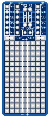
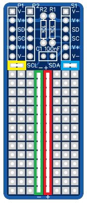
The pads highlighted to the left have the following connections:
- Red = V+ (5 volts)
- Green = V- (0 volts / ground)
- Yellow = I2C serial clock (SCL)
- Blue = I2C serial data (SDA)
Downloads
- SC401 – Kit contents sheet (PDF)
- SC401 – Printed circuit board Gerber files
- SC401 – Schematic v1.0 (PDF)
- Example code: see SC400 series details
Suppliers
| Kits | Website | From | Currency |
| Small Computers Direct | SCDirect | UK | GBP |
| Stephen C Cousins | Tindie | UK | USD |
| Small Computer Central | Lectronz | UK | Euro/USD |
| PCBs | Website | From | Currency |
| Small Computers Direct | SCDirect | UK | GBP |
| Stephen C Cousins | Tindie | UK | USD |
| Small Computer Central | Lectronz | UK | Euro/USD |
| Assembled and Tested | Website | From | Currency |
| Not available | |||
| Components | |||
| See parts list |
Tindie does not collect VAT for EU countries
Lectronz does collect EU VAT for orders up to 150 EUR
Parts List
| Reference | Qty | Component |
| PCB | 1 | SC401, v1.0, PCB Design at OSHWLab |
| C1 | 1 | Capacitor, ceramic, 100 nF |
| P1 | 1 | Header, male, 2 row x 6 pin, angled The second row of pins needs to be removed. |
| P2 | 1 | Header, male, 1 row x 6 pin, straight |
| R1 and R2 | 2 | Resistor, 10k, 0.25W Optional |
| S1 | 1 | Header, female, 1 row x 6 pin, angled |
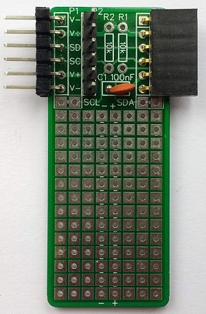
Assembly
This design is so simple it does not justify a detailed assembly guide. Just assemble according to the photo above.
In order for the daisy-chained PCBs to be a consistent level, header pins (P1) need to have a profile that matches the socket (S1). By far the most common angled header pins do not match. A suitable profile header can be created by removing the second row of pins from a double row header. The pins can easily be pulled out of the plastic guide with a small pair of pliers.
The two resistors, R1 and R2, are not normally required. These are pull up resistors for the I2C bus signals, serial clock and serial data. The pull up resistors typically found on I2C bus masters are usually all that is required. However, should you require additional resistors for any reason, they can be fitted here. The most likely reason to add resistors is to terminate a long bus with many devices connected.
Notes
- This product is designed for hobby use and is not suitable for industrial, commercial or safety-critical applications.
- The product contains small parts and is not suitable for young children.
