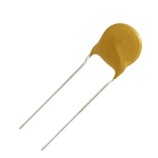
Ceramic capacitors can be fitted either way around as they are not polarity dependent.
Electrolytic capacitors must be fitted the correct way around. They have the negative terminal indicated with a ‘minus’ sign. The negative terminal also has a shorter lead.

18 pF, Ceramic, >15 Volts
Label typically includes “18”
Lead spacing 2.54mm (0.1″)
22 pF, Ceramic, >15 Volts
Label typically includes “22”
Lead spacing 2.54mm (0.1″)
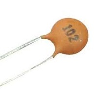
1 nF, Ceramic, >15 Volts
Label typically includes “102”
Lead spacing 2.54mm (0.1″)
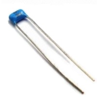

100 nF, Ceramic, >15 Volts
Label typically includes “104”
Lead spacing 2.54mm (0.1″)
Typically used for supply decoupling
Colour and shape vary
Ceramic 100 nF (0.1 µF) capacitors are typically used for supply decoupling. For digital circuits operating in the range of 7 to 18 MHz (as generally used by the designs on this site) the use of very cheap ceramic capacitors within the range of about 30 to 200 nF is acceptable.
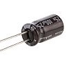
100 µF, Electrolytic, >15 Volts
Label typically includes “100 µF”
Lead spacing 2.54mm (0.1″)
