Compact Flash cards are often used by 8-bit retro computers to store programs and files. The designs on this site use a Compact Flash adapter, as illustrated below. This avoids the need to solder the fine pins of the surface mount Compact Flash connector. Note the required jumper positions.

There are two types of this adapter that look the same but have a critical difference. One type allows the adapter, and thus the Compact Flash card, to be powered from the 40-pin connector, while the other does not. The 40-pin connector is at the bottom of the adapter as illustrated above.
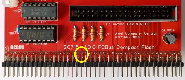
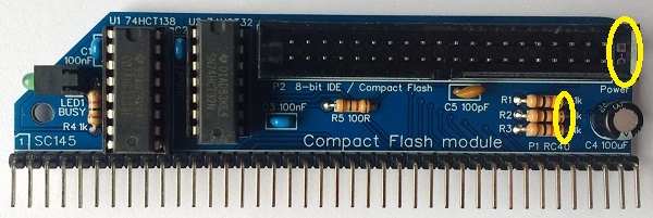
The type can be identified by looking at pin 20 of the 40-pin connector, as illustrated below. If the hole is blocked the adapter can not be powered from this connector. In fact, it can’t even be plugged in to a 40-pin header without either the header pin being removed or the hole being unblocked.
Typically, this type of adapter is used to replace a hard drive in a PC, where the power is supplied from a standard 4-pin disk drive power connector, as shown at the top right of the first photo above.
Unfortunately, just removing the blockage from the connector does not allow the adapter to be powered from the 40-pin connector. This is because to contacts have been removed from pin 20. However, there are a number of solutions to the problem.
The following solutions require one, but not both, of the following to be done before connecting the wire link or Dupont cable:
- Remove pin 20 from the IDE header on the RCBus module, as described below. See note below about SC504.
- Remove the blockage from the Compact Flash adapter. Take great care not to damage the Compact Flash adapter.
SC504 only: If a box header, rather than header pins, is used for the IDE connector, be aware that the key slot is on the wrong side for this particular application. The Compact Flash adapter’s key stud needs to be cut or filed off. See assembly guide for details. Do this before removing pin 20.
If the header has not been soldered to the PCB the easy way to remove pin 20 is simply to push the adapter onto the header pins, as shown below. Keep the removed pin in case you want to put it back later.

If the header has already been soldered to the PCB then, in the case of header pins, cut the pin with wire cutters, or, in the case of a box header, bending the pin from side to side until it breaks seems to work well.
There are a number of options for connecting 5 volts to the adapter, as described below.
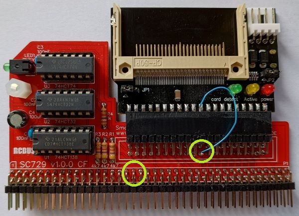
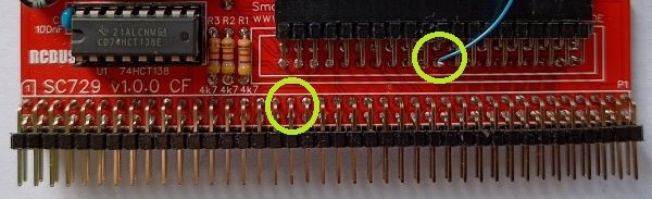
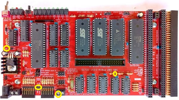
One solution to powering the Compact Flash adapter is to link pin 20 on the adapter to a convenient 5 volt point on the RCBus module. This is illustrated below with SC729. An alternative 5 volt point would be the RCBus header pin 18.
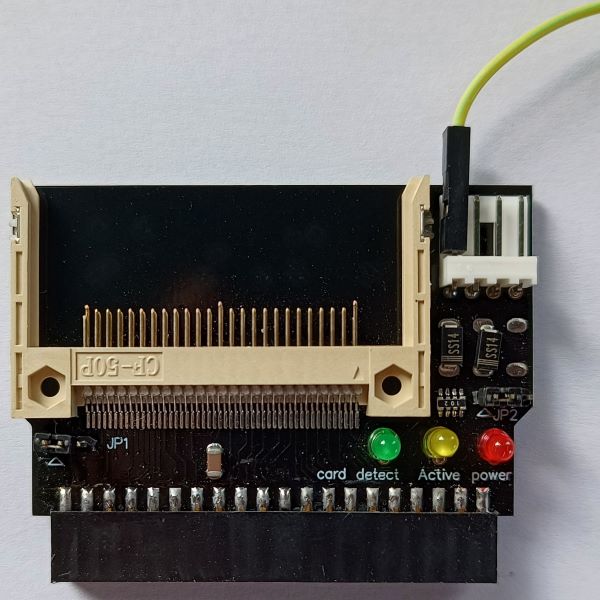
Another solution is to use the 4-pin power connector as illustrated below. In this case a Dupont cable is used to connect the 5 volt power to the adapter. The other end of the Dupont cable can be connected to any available 5 volt header pin (most systems will have one somewhere) or solder it to a convenient 5 volt pin or pad.
Actually, these adapters usually work without the direct 5 volt connection but I can’t really recommend this.
Some of the suitable 5 volt pins and pads are indicated below.
Power from 20 pin IDE header or pin 18/58 of the RCBus on the front of the PCB
or any 5 volt pin or pad on the back of the PCB
Power from pin 18/58 of the RCBus on the front of the PCB
or any 5 volt pin or pad on the back of the PCB
Power from pads JP1 or the resistors on the front of the PCB
or any 5 volt pin or pad on the back of the PCB
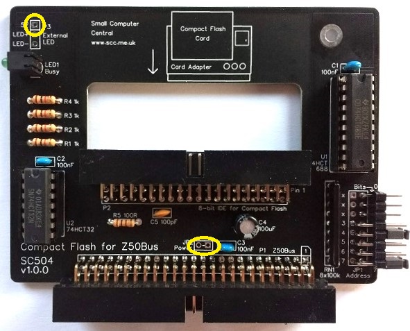
Power from pads JP2 or JP3 pin 1 on the front of the PCB
or any 5 volt pin or pad on the back of the PCB
Also worth a read: notes about Compact Flash reliability.
